
 J I A N G S U U N I V E R S I T Y
数字逻辑课程设计
-多功能数字钟
学院名称: 计算机科学与通信工程
专业班级: 通信0902
学生姓名:
学生学号:
指导老师: 赵念强
完成日期: 20##年7月2日
多功能数字钟课程设计实验报告
一. 实验目的:
1. 学会应用数字系统设计方法进行电路设计;
2. 进一步提高MAX+plus II 10.0 BASELINE软件的开发应用能力;
3. 培养学生书写综合实验报告的能力。
二. 实验要求:
1. 根据实验任务,选择最佳设计方案,综合运用MAX+plus II 10.0 BASELINE软件的各种设计方法设计出层次分明、结构清楚、电路优化、VHDL语言描述简洁的完整设计文件。通过仿真直至下载来验证设计的正确性。
三. 实验任务及要求
1. 能进行正常的时、分、秒计时功能
(1) 用M6M5做24小时计数器的显示器;
(2) 用M4M3做60分钟计数器的显示器;
(3) 用M2M1做60秒钟计数器的显示器。
2. 能利用实验系统上的按键实现“校时”、“校分”功能
(1) 按下“SA”键时,计时器迅速递增,并按24小时循环,计满23小时后再回00;
(2) 按下“SB”键时,计时器迅速递增,并按60分钟循环,计满59分钟后再回00;但不向高位进位。
(3) 按下“SC” 键后,秒清零。要求按下“SA”和“SB”均不会产生数字跳变(“SA”、“SB”按键是有抖动的,必须地“SA”、“SB”进行消抖处理, 消抖电路用D触发器构成。 原理:一个触发器CP(64HZ)内,屏蔽所有的抖动脉冲)。
(4) 计时(24进制计数器),计分(60进制计数器)、计秒(60进制计数器)模块可由10进制计数器连接构成,也可用VHDL语言完成(可以参考教材P341,例8.2.1 多功能电子钟的设计)。10进制计数器需自己设计(用VHDL语言,与所做实验74160计数器相同),不能调用系统库。
(5) 其他如分频电路、提供报时控制信号、闹时电路等模块用VHDL语言实现。
3. 能利用实验板上的扬声器作整点报时
(1) 当计时到达59’50”、 51”、 52”、 53”、54”、55”、 56”、 57”、 58”、59”鸣叫,鸣叫声频可定为500HZ;
(2) 到达00分00秒时为最后一声整点报时。整点报时的频率可定为1KHZ。报时信号从ISP1032的PIN68输出,PIN68与扬声器的输入电路相连,激励扬声器;
4. 闹时
(1) 闹时的最小时间间隔为十分钟。
(2) 闹时长度为一分钟。
(3) 闹时声响可以是单频。
(4) 闹时时声响也可以是双频交替的警笛声。
5. 使用MAX+plus II 10.0 BASELINE软件设计符合上述功能的多功能数字钟,并用层次化设计方法设计该电路。
6. 报时功能。闹时功能用功能仿真的方法验证,可通过观察有关波形确认电路设计是否正确。
7. 使用设计思路----层次化的思想: 计时(间)模块、时间校对模块、报时模块、分频模块、动态显示模块
(1)
8. 完成全部电路设计后在EP1KTC144-3 实验系统上下载,验证设计的正确性。
四.顶层图及相关模块说明:
1. 顶层图:


说明:程序下载后自动进入计时状态,sa,sb,sc可分别调时,分,秒。
2.各模块说明:
(1)进制模块:
1.十进制源程序:
library ieee;
use ieee.std_logic_1164.all;
use ieee.std_logic_unsigned.all;
entity ls160 is
port
(
data : in std_logic_vector(3 downto 0);
clk,ld,p,t,clr : in std_logic;
count : buffer std_logic_vector(3 downto 0);
tc:out std_logic);
end ls160;
architecture behavior of ls160 is
begin
tc<='1' when (count ="1001" and p='1' and t='1' and ld='1' and clr='1') else '0';
cale:
process(clk,clr,p,t,ld)
begin
if(rising_edge(clk)) then
if(clk='1') then
if(ld='1') then
if(p='1') then
if(t='1') then
if(count="1001") then
count<="0000";
else
count<=count+1;
end if;
else
count<=count;
end if;
else
count<=count;
end if;
else
count<=data;
end if;
else
count<="0000";
end if;
end if;
end process cale;
end behavior;
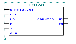
十进制生成器件
2. 二十四进制:
电路图:
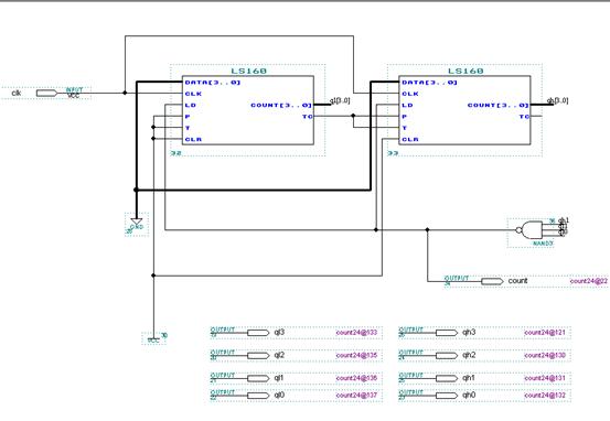
生成器件:

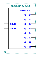
3. 六十进制:
电路图:
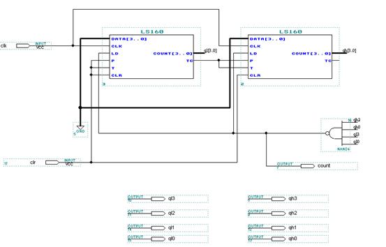
生成器件:
模块说明:此计数器由两个十进制计数器构成,片一的进位TC独立与片二的P,T连在一起,并行连接成一百进制计数器,片一的P,T接高电平,两片的CLK都接在同一输入上,形成异步置零。片一上的AD,片二上的AC接入同一与非门,再接到两片的LD上。H[3…0]构成十位,L[3…0]构成个位。
(2)DTSM模块:
dtsh源程序:
library ieee;
use ieee.std_logic_1164.all;
use ieee.std_logic_arith.all;
use ieee.std_logic_unsigned.all;
entity dtsm is
port(clk:in std_logic;
s :in std_logic_vector(7 downto 0);
f :in std_logic_vector(7 downto 0);
m :in std_logic_vector(7 downto 0);
selout:out std_logic_vector(5 downto 0);
segout:out std_logic_vector(6 downto 0)
);
end dtsm;
architecture a of dtsm is
signal number:std_logic_vector(3 downto 0);
signal sel :std_logic_vector(5 downto 0);
signal seg :std_logic_vector(6 downto 0);
signal q :std_logic_vector(2 downto 0);
begin
a:process(clk)
begin
if(clk'event and clk='1')then
q<=q+1;
end if;
end process a;
process(q)
begin
case q is
when"000"=>sel<="000001";
when"001"=>sel<="000010";
when"010"=>sel<="000100";
when"011"=>sel<="001000";
when"100"=>sel<="010000";
when"101"=>sel<="100000";
when others=>sel<="000000";
end case;
end process;
process
begin
if sel ="000001"then
number<=m(3 downto 0);
elsif sel="000010"then
number<=m(7 downto 4);
elsif sel="000100"then
number<=f(3 downto 0);
elsif sel="001000"then
number<=f(7 downto 4);
elsif sel="010000"then
number<=s(3 downto 0);
elsif sel="100000"then
number<=s(7 downto 4);
else
number<="1111";
end if;
end process;
process(number)
begin
case number is
when"0000"=>seg<="0111111";
when"0001"=>seg<="0000110";
when"0010"=>seg<="1011011";
when"0011"=>seg<="1001111";
when"0100"=>seg<="1100110";
when"0101"=>seg<="1101101";
when"0110"=>seg<="1111101";
when"0111"=>seg<="0000111";
when"1000"=>seg<="1111111";
when"1001"=>seg<="1101111";
when others=>seg<="0000000";
end case;
end process;
selout<=sel;
segout<=seg;
end a;
生成器件:
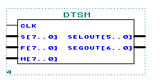
端口说明:
s,f,m分别为时、分、秒的输入端,定义为std_logic_vector(7 downto 0);segout为七端显示管的输出,定义为std_logic_vector(6 downto 0);selout为扫描地址端,定义为std_logic_vector(5 downto 0),某一时刻只有一个为1,对应的数组号即为当前扫描的数码管的编号。
功能实现:
定义一个std_signa_vector(2 downto 0)变量q,它在0至5之间不断的循环,用来指示当前扫描的哪一根管, 循环用语句if q>=5 then q<="000"; else q<=q+1; end if;实现。再定义一个类型为std_logic_vector(5 downto 0)的sel信号,它用来产生一个长度为6的数,该数在同一时刻只有一位是高电平表示正在扫描该显示管,在进程结束时它的值将赋给selout输出。定义一个std_logic_vector(6 downto 0)类型的seg,用来存放将由四位bcd码编码而来的七段显示码。最后在进程中定义一个std_logic_vector(3 downto 0)类型的number变量,用来存放时、分、秒的高位或低位,然后将该数编码成七段显示码,并赋给seg信号。具体算法如下:建立一个以clk脉冲为敏感变量的进程,先判断是否是clk的高电平脉冲,若不是则什么也不执行,若是高电平脉冲,则执行以下程序。P加1,用case语句根椐p的值,给number赋予当前要扫描的数码管的值,用case语句根椐number的值编译成对应的七段显示管的值并赋给seg,当进程结束时把seg的值赋给segout,把sel的值赋给selout,然后由这两个端口输出。
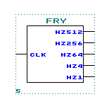
(3)分频模块:
分频器源程序:
library ieee;
use ieee.std_logic_1164.all;
use ieee.std_logic_arith.all;
use ieee.std_logic_unsigned.all;
entity fry is
port(clk:in std_logic;
hz512:out std_logic;
hz256:out std_logic;
hz64:out std_logic;
hz4:out std_logic;
hz1:out std_logic
);
end fry;
architecture f of fry is
signal q:std_logic_vector(9 downto 0);
begin
process(clk)
begin
if clk'event and clk='1'then
q<=q+1;
end if;
end process;
hz512<=q(0);
hz256<=q(1);
hz64<=q(3);
hz4<=q(7);
hz1<=q(9);
end f;
生成器件:
(4)报时模块:
报时器源程序:
library ieee;
use ieee.std_logic_1164.all;
use ieee.std_logic_arith.all;
use ieee.std_logic_unsigned.all;
entity alert is
port(m1,m0,s1,s0 : in std_logic_vector(3 downto 0);
sig500,sig1k : out std_logic);
end alert;
architecture a of alert is
signal q : std_logic_vector(15 downto 0);
signal s500,s1k : std_logic;
begin
q(15 downto 12)<=m1;
q(11 downto 8)<=m0;
q(7 downto 4)<=s1;
q(3 downto 0)<=s0;
hring : block
begin
s500<='1' when q="0101100101010000" else
'1' when q="0101100101010010" else
'1' when q="0101100101010100" else
'1' when q="0101100101010110" else
'1' when q="0101100101011000" else
'0';
s1k<='1' when q="0000000000000000" else
'0';
end block hring;
sig500<=s500;
sig1k<=s1k;
end a;
生成器件:
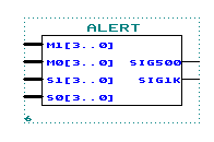
闹钟报时系统:
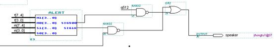
模块说明:
由于clk的频率为1024hz,所以可以定义一个std_logic_vector(9 downto 0),使它不停地从0000000000加到1111111111然后又返回0000000000,由于最低位在clk脉冲到来时从0变为1,然后又在下一个脉冲变回0,因此最低位的时钟周期为clk的时钟周期的两倍,它的频率就为clk频率的确1/2即512hz。同理,次高位的频率就为clk频率的1/2 * 1/2 = 1/4,用这种方法就可以得到各种能整除1024的频率,从而实现分频。
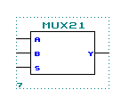
(5)二路选择器
源程序:
LIBRARY IEEE;
USE IEEE.STD_LOGIC_1164.ALL;
ENTITY mux21 IS
PORT ( a , b ,s: IN STD_LOGIC ;
y : OUT STD_LOGIC );
END ENTITY mux21;
ARCHITECTURE one OF mux21 IS
BEGIN
PROCESS(a,b,s)
BEGIN
IF s = '0' THEN
y<=a; ELSE
y<=b;
END IF;
END PROCESS;
END ARCHITECTURE one;
生成器件:
五.课程设计感想: