
EDA实训报告

一、实训目的
1、了解数字钟的工作原理。
2、进一步熟悉用VHDL语言编写驱动七段码管显示的代码。
3、掌握VHDL编写中的一些小技巧。
二、实训原理
多功能数字钟应该具有的功能有:显示时-分-秒、整点报时、小时和分钟可调等基本功能。首先要知道钟表的工作机理,整个钟表的工作应该是在1Hz信号的作用下进行,这样每来一个时钟信号,秒增加1秒,当秒从59秒跳转到00秒时,分钟增加1分,同时当分钟从59分跳转到00分时,小时增加1小时,但是需要注意的是,小时的范围是从0~23时。
在实训中为了显示的方便,由于分钟和秒钟显示的范围都是从0~59,所以可以用一个3位的二进制码显示十位,用一个四位的二进制码(BCD码)显示个位,对于小时因为它的范围是从0~23,所以可以用一个2位的二进制码显示十位,用4位二进制码(BCD码)显示个位。
实训中由于七段码管是扫描的方式显示,所以虽然时钟需要的是1Hz时钟信号,但是扫描确需要一个比较高频率的信号,因此为了得到准确的1Hz信号,必须对输入的系统时钟进行分频。
对于整点报时功能,用户可以根据系统的硬件结构和自身的具体要求来设计。本实训设计的是当进行整点的倒计时5秒时,让LED来闪烁进行整点报时的提示。
三、实训内容
本实验的任务就是设计一个多功能数字钟,要求显示格式为 小时-分钟-秒钟,整点报时,报时时间为10秒,即从整点前10秒钟开始进行报时提示,喇叭开始发声,直到过整点时,在整点前5秒LED开始闪烁,过整点后,停止闪烁。调整时间的的按键用按键模块的S1和S2,S1调节小时,每按下一次,小时增加一个小时,S2调整分钟,每按下一次,分钟增加一分钟。另外用按键作为系统时钟复位,复位后全部显示00-00-00。
四、实训步骤
1、写出数码管显示的程序部分。
2、写出数字钟的程序部分。
3、写出调时和蜂鸣器程序部分。
4、管脚分配和下载实验。
5、修改程序,简化,写注释。
五、实训VHDL程序
library ieee;
use ieee.std_logic_1164.all;
use ieee.std_logic_arith.all;
use ieee.std_logic_unsigned.all;
entity shizhong is
port(sr:out std_logic_vector(0 to 6);
led:out std_logic_vector(0 to 3);
tr:out std_logic_vector(0 to 5);
clk:in std_logic;
c1,c2,c3,c4:in std_logic;
speak:out std_logic);
end shizhong;
architecture behave of shizhong is----结构体
signal disp_temp :integer range 0 to 10;
signal sec1m,sec10m :integer range 0 to 9:=0;----秒的个位和十位信号
signal sec1,sec10 :integer range 0 to 10:=0;----------
signal hor1,hor10 :integer range 0 to 10:=0;
signal clk1khz:std_logic;---1KHz信号
signal clk1hz:std_logic;----1HZ信号
signal st:std_logic;
signal display :integer range 0 to 5;
signal k1,k2:std_logic_vector(2 downto 0);
signal k3:std_logic;
signal f1:std_logic_vector(1 downto 0);
signal cink: integer range 0 to 100;
BEGIN
--------------------------------------------------------50MHz分频出1Hz信号
PROCESS(clk)
variable cnt:integer range 0 to 49999999;
begin
if clk='1' and clk'event then
if cnt=49999999 then cnt:=0;
else
if cnt<25000000 then clk1hz<='1';
else clk1hz<='0';
end if;
cnt:=cnt+1;
end if;
end if;
end process;
--------------------------------------------------------50MHz分频出1KHz信号
PROCESS(clk)
variable cnt1:integer range 0 to 49999;
begin
if clk='1' and clk'event then
if cnt1=49999 then cnt1:=0;
else
if cnt1<25000 then clk1khz<='1';cink<=cink+1 ;if cink>=100 then cink<=0;end if;
else clk1khz<='0';
end if;
cnt1:=cnt1+1;
end if;
end if;
end process;
----------------------------------------------------------
process(clk1hz)
variable s1,s2,s3,s4,s5,s6:integer range 0 to 9;
begin
if clk1hz='1' and clk1hz'event then
if s1>=9 and s2>=5 then s1:=0;s2:=0;
if s3>=9 and s4>=5 then s3:=0;s4:=0;
if s5>=3 and s6>=2 then s5:=0;s6:=0;
elsif s6>2 then s6:=0;
elsif s5>=9 then s5:=0;s6:=s6+1;
else s5:=s5+1;end if;
elsif s3>=9 then s3:=0;s4:=s4+1;
else s3:=s3+1;end if;
elsif s1>=9 then s1:=0;s2:=s2+1;
else s1:=s1+1;end if;
if s3>9 and s4>5 then s3:=0;s4:=0;end if;
if s5>3 and s6>2 then s5:=0;s6:=0;end if;
if s6>2 then s6:=0;end if;
if s5>9 then s5:=0;end if;
if s3>9 then s3:=0;end if;
if s4>5 then s4:=0;end if;
if c1='0' then s3:=s3+1;end if;
if c2='0' then s4:=s4+1;end if;
if c3='0' then s5:=s5+1;end if;
if c4='0' then s6:=s6+1;end if;
sec1m<=s1;sec10m<=s2;sec1<=s3;sec10<=s4;hor10<=s6;hor1<=s5;
end if;
end if;
if s3=0 and s4=0 and s1<5 and s2=0 then speak<='0';led<="1111";
else speak<='1';led<="0000";end if;
end process;
----------------------------------------------------------
process(display)
begin
case(display) is
when 0=>disp_temp<=hor10;tr<="011111";
when 1=>disp_temp<=hor1;tr<="101111";
when 2=>disp_temp<=sec10;tr<="110111";
when 3=>disp_temp<=sec1;tr<="111011";
when 4=>disp_temp<=sec10m;tr<="111101";
when 5=>disp_temp<=sec1m;tr<="111110";
when others=>tr<="111111";
end case;
end process;
----------------------------------------------------------
process(clk1khz)
begin
if(clk1khz'event and clk1khz='1') then
if display=5 then display<=0;
else
display<=display+1;
end if;
end if;
end process;
process(disp_temp)
begin
case disp_temp is
when 0=>sr<="1000000";
when 1=>sr<="1111001";
when 2=>sr<="0100100";
when 3=>sr<="0110000";
when 4=>sr<="0011001";
when 5=>sr<="0010010";
when 6=>sr<="0000010";
when 7=>sr<="1111000";
when 8=>sr<="0000000";
when 9=>sr<="0010000";
when others=>sr<="1111111";
end case;
end process;
end behave;
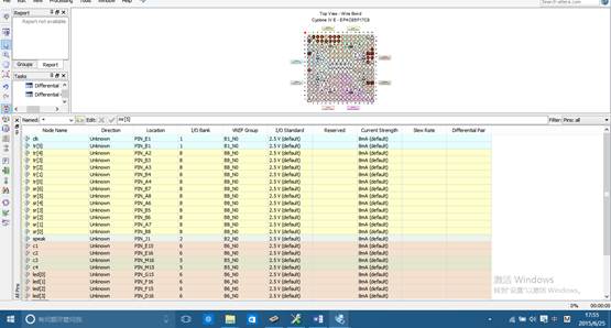
六、管脚分配
七、实训结果
本实验的任务就是设计一个多功能数字钟,要求显示格式为 小时-分钟-秒钟,整点报时,报时时间为10秒,即从整点前10秒钟开始进行报时提示,喇叭开始发声,直到过整点时,在整点前5秒LED开始闪烁,过整点后,停止闪烁。调整时间的的按键用按键模块的S1和S2,S1调节小时,每按下一次,小时增加一个小时,S2调整分钟,每按下一次,分钟增加一分钟。另外用按键作为系统时钟复位,复位后全部显示00-00-00。
八、实训总结
通过本次实验对软件EDA软件有了更深的了解,掌握在Quartus Ⅱ中VHDL语句 VHDL语句的编写、仿真方法和层次设计的意义。
在实现不同电路的功能时,使用不同的语句其实际电路是不一样的,在语句的编写过程中如果可以使用”=”,就尽量避免” >”或”<”的使用,这样可以减小对硬件的占用。类似的问题还有很多,在语句描写的时候,不仅仅要考虑功能的实现,减小对硬件的使用量也是非常重要的。
VHDL中尽量不要使用乘除法,避免消耗大量LE,一个进程中只能有一个边沿检测event,编写程序是要尤其注意,VHDL为顺序执行结构,编写程序时,尽可能多的使用进程能增加程序的执行效率。
这次试验收获了很多,养成严谨以及对事物的细心观察的习惯,对问题的解决可以有很大的帮助。
第二篇:EDA仿真实践报告
```` 大 学
EDA技术实践课程设计

年 7月 25日
EDA技术实践课程设计任务书
课程 EDA技术实践课程设计
题目 四人抢答器的设计
专业 电气工程及其自动化 姓名 学号
主要内容:
根据仿真软件EDA 的主要功能特点,利用其丰富的材料库和先进的仿真功能设计一个四人抢答器,并对设计出来的抢答器进行仿真分析和检验。
基本要求:
(1)设计制作一个可容纳四组参赛者的数字智力抢答器,每组设置一个抢答按钮供抢答者使用。
(2)电路具有第一抢答信号的鉴别和锁存功能。
(3)系统具有计分电路。
主要参考资料:
[1] 潘松.EDA技术与VHDL(第2版)[M]. 清华大学出版社.2007
[2] 曹昕燕.EDA技术实验与课程设计[M]. 清华大学出版社. 2006
[3] 张昌凡,龙永红,彭涛.可编程逻辑器件及VHDL设计技术[M].广州:华南工学院出版社,2001.
[4] 彭介华.电子技术课程设计指导[M].北京:高等教育出版社,1997 .
[5] 卢杰,赖毅.VHDL与数字电路设计[M]..北京:科学出版社,2001
完成期限
指导教师
专业负责人
年 7 月18日
目 录
1 设计... 1
2 方案选择与电路原理图的设计... 1
2.1 抢答鉴别模块方案的选择... 1
2.2 抢答计时模块方案选择... 3
2.3 抢答计分模块方案选择... 5
2.4 译码显示模块方案确定... 8
2.4电路原理图设计... 9
3 电路图的绘制... 9
3.1 电路图的绘制... 9
4 仿真分析方法实验与结果分析... 11
4.1抢答鉴别模块的时序仿真图... 11
4.2抢答计时模块时序仿真图... 11
4.3抢答计分模块的时序仿真图... 12
5 总结... 12
参考文献... 14
1 设计
系统的输入信号有:各组的抢答按钮A、B、C、D,系统清零信号CLR,系统时钟信号CLK,计分复位端RST,加分按钮端ADD,计时预置控制端LDN,计时使能端EN,计时预置数据调整按钮可以用如TA、TB表示;系统的输出信号有:四个组抢答成功与否的指示灯控制信号输出口可用如LEDA、LEDB、LEDC、LEDD表示,四个组抢答时的计时数码显示控制信号若干,抢答成功组别显示的控制信号若干,各组计分动态显示的控制信号若干。整个系统至少有三个主要模块:抢答鉴别模块、计时模块、抢答计分模块。
2 方案选择与电路原理图的设计
2.1 抢答鉴别模块方案的选择
抢答队伍共分为四组A,B,C,D。当主持人按下START键后,四组队伍才可以按抢答键抢答。抢答成功后表示该组的指示灯见亮起,但在主持人未按下START键之前,所有的抢答键按下均是无效的。当任意一个组抢答成功后,其余的组按抢答键无效。抢答键为A,B,C,D四个键。
其源程序编写如下:
library ieee;
use ieee.std_logic_1164.all;
entity jb is
port(sta:in std_logic;
rst:in std_logic;
a,b,c,d:in std_logic;
a1,b1,c1,d1:out std_logic;
states: out std_logic_vector(3 downto 0);
start: out std_logic);
end entity jb;
architecture art of jb is
constant w1: std_logic_vector:="0001";
constant w2: std_logic_vector:="0010";
constant w3: std_logic_vector:="0100";
constant w4: std_logic_vector:="1000";
signal sinor: std_logic;
signal nsinor: std_logic;
signal s_start: std_logic;
begin
sinor<=a or b or c or d;
nsinor<=not(a or b or c or d);
start<=s_start;
process(sta,nsinor) is
begin
if (sta='1') then
s_start<='1';
elsif(nsinor'event and nsinor='1')then
s_start<='0';
end if;
end process;
process(rst,sta,sinor,nsinor) is
begin
if(rst='1' or sta='1' or nsinor='1')then
a1<='0';b1<='0';c1<='0';d1<='0';
elsif(sinor'event and sinor='1')then
if(s_start='1')then
if(a='1')then
a1<='1';b1<='0';c1<='0';d1<='0';
elsif(b='1')then
a1<='0';b1<='1';c1<='0';d1<='0';
elsif(c='1')then
a1<='0';b1<='0';c1<='1';d1<='0';
elsif(d='1')then
a1<='0';b1<='0';c1<='0';d1<='1';
end if;
end if;
end if;
end process;
process(sinor) is
begin
if(rst='1')then
states<="0000";
elsif(sinor'event and sinor='1')then
if(s_start='1')then
if(a='1')then
states<=w1;
elsif(b='1')then
states<=w2;
elsif(c='1')then
states<=w3;
elsif(d='1')then
states<=w4;
end if;
end if;
end if;
end process;
end architecture art;
2.2 抢答计时模块方案选择
主持人宣布抢答成功后,按下EN键,选手开始回答,系统开始计时。TA和TB键选择计时的时间(TA:9秒,TB:7秒)。
其源程序的编写如下:
library ieee;
use ieee.std_logic_1164.all;
use ieee.std_logic_unsigned.all;
entity js is
port(clr,ldn,en,clk:in std_logic;
ta,tb: in std_logic;
qa: out std_logic_vector(3 downto 0);
qb: out std_logic_vector(3 downto 0));
end entity js;
architecture art of js is
signal da: std_logic_vector(3 downto 0);
signal db: std_logic_vector(3 downto 0);
begin
process(ta,clr) is
begin
if(clr='1')then
da<="1001";
elsif(ta'event and ta='1')then
if(ldn='1')then
if(da="0000")then
da<="1001";
else
da<=da-1;
end if;
end if;
end if;
end process;
process(tb,clr) is
begin
if(clr='1')then
db<="0101";
elsif(tb'event and tb='1')then
if(ldn='1')then
if db="0000"then
db<="1001";
else
db<=db-1;
end if;
end if;
end if;
end process;
process(clk) is
variable tmpa: std_logic_vector(3 downto 0);
variable tmpb: std_logic_vector(3 downto 0);
begin
if(clr='1')then
tmpa:="0000";
tmpb:="0000";
elsif clk'event and clk='1' then
if en='1'then
tmpa:=da;
tmpb:=db;
elsif tmpa="0000"then
if tmpb="0000"then
tmpa:="0000";
else
tmpa:="1001";
end if;
if tmpb="0000"then
tmpb:="0000";
else
tmpb:=tmpb-1;
end if;
else
tmpa:=tmpa-1;
end if;
end if;
qa<=tmpa;
qb<=tmpb;
end process;
end architecture art;
2.3 抢答计分模块方案选择
主持人确认选手回答正确后,按下ADD键为选手加分。
其源程序编写如下:
library ieee;
use ieee.std_logic_1164.all;
use ieee.std_logic_unsigned.all;
entity jf is
port(rst: in std_logic;
add: in std_logic;
chose: in std_logic_vector(3 downto 0);
aa2,aa1,aa0,bb2,bb1,bb0: out std_logic_vector(3 downto 0);
cc2,cc1,cc0,dd2,dd1,dd0: out std_logic_vector(3 downto 0));
end entity jf;
architecture art of jf is
begin
process(rst,add,chose) is
variable a2,a1:std_logic_vector(3 downto 0);
variable b2,b1:std_logic_vector(3 downto 0);
variable c2,c1:std_logic_vector(3 downto 0);
variable d2,d1:std_logic_vector(3 downto 0);
begin
if(rst='1')then
a2:="0001";a1:="0000";
b2:="0001";b1:="0000";
c2:="0001";c1:="0000";
d2:="0001";d1:="0000";
elsif(add'event and add='1')then
if chose="0001"then
if a1="1001"then
a1:="0000";
if a2="1001"then
a2:="0000";
else
a2:=a2+'1';
end if;
else
a1:=a1+'1';
end if;
elsif chose="0010"then
if b1="1001"then
b1:="0000";
if b2="1001"then
b2:="0000";
else
b2:=b2+'1';
end if;
else
b1:=b1+'1';
end if;
elsif chose="0100"then
if c1="1001"then
c1:="0000";
if c2="1001"then
c2:="0000";
else
c2:=c2+'1';
end if;
else
c1:=c1+'1';
end if;
elsif chose="1000"then
if d1="1001"then
d1:="0000";
if d2="1001"then
d2:="0000";
else
d2:=d2+'1';
end if;
else
d1:=d1+'1';
end if;
end if;
end if;
aa2<=a2;aa1<=a1;aa0<="0000";
bb2<=b2;bb1<=b1;bb0<="0000";
cc2<=c2;cc1<=c1;cc0<="0000";
dd2<=d2;dd1<=d1;dd0<="0000";
end process;
end architecture art;
2.4 译码显示模块方案确定
译码显示模块用于显示每组选手的分数,计时的的时间等信息。
其源程序编写如下:
library ieee;
use ieee.std_logic_1164.all;
use ieee.std_logic_unsigned.all;
entity ym is
port(in4: in std_logic_vector(3 downto 0);
out7:out std_logic_vector(6 downto 0));
end ym;
architecture art of ym is
begin
process(in4)
begin
case in4 is
when"0000"=>out7<="0111111";
when"0001"=>out7<="0000110";
when"0010"=>out7<="1011011";
when"0011"=>out7<="1001111";
when"0100"=>out7<="1100110";
when"0101"=>out7<="1101101";
when"0110"=>out7<="1111101";
when"0111"=>out7<="0000111";
when"1000"=>out7<="1111111";
when"1001"=>out7<="1101111";
when others=>out7<="0000000";
end case;
end process;
end architecture;
2.4电路原理图设计
电路设计原理框图如图2.1所示。
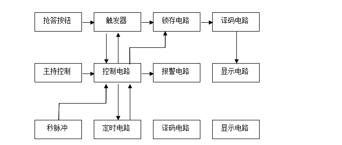


图2.1 电路原理框图
3 电路图的绘制
3.1 电路图的绘制
1、顶层原理图
整个系统的大致组成图如图3.1所示。

图3.1 顶层原理图
4 仿真分析方法实验与结果分析
4.1抢答鉴别模块的时序仿真图

抢答鉴别模块的时序仿真图如图4.1所示。
图4.1 抢答鉴别模块的时序仿真图
抢答开始后,A组按下抢答键,抢答成功。
4.2抢答计时模块时序仿真图
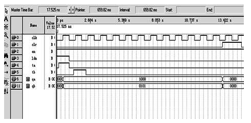
抢答计时模块的时序仿真图如图4.2所示。
图4.2 抢答计时模块的时序仿真图
按下EN开始答题,回答问题时,选择TA模式计时。
4.3抢答计分模块的时序仿真图

抢答计分模块的时序仿真图如图4.2所示。
图4.2 抢答计分模块时序仿真图
A组回答正确,加分。
5 总结
本课程设计就EDA系统进行原理图设计,使用EDA软件(或硬件)进行了仿真,验证了设计的合理性和可行性。具体内容包括:
1、设计了四人抢答系统的主电路和控制电路,包括抢答鉴别模块;抢答计时模块;抢答计分模块;
2、根据设计任务指标计算了各部分系统参数;
3、收获与体会:
本次的EDA课程设计历时间虽短,但通过一个星期的实践,使我对EDA技术有了更进一步的了解。同时,大致懂得了一个课题制作的具体流程和实施方法。另外,课程设计对QuartusⅡ软件的使用要求较高,从而使我能较为熟练的运用此软件。在设计时,采用模块化的设计思路使得问题变的简单明了,大大缩短了时间,降低了发生错误的几率,也便于修改和更新。
通过这次对抢答器的设计和实践,学到了很多的东西,不仅巩固了以前所学的知识,而且学到了书本上没有的东西,有些知识书本写的很简洁,但实际操作起来却是另外一种感觉,真是体现了“纸上得到终觉浅,绝知此事要躬行”这句话的含义。在这次设计,把理论与实践信结合起来,在老师的指导下和视频学习下,有些关键的问题才得以解决,锻炼了自己的能力,对以后走的路有了更清楚的认识,同时有了更多的信心。
参考文献
[1] 潘松.EDA技术与VHDL(第2版)[M]. 清华大学出版社.2007.
[2] 曹昕燕.EDA技术实验与课程设计[M]. 清华大学出版社. 2006.
[3] 张昌凡,龙永红,彭涛.可编程逻辑器件及VHDL设计技术[M].广州:华南工学院出版社,2001.
[4] 彭介华.电子技术课程设计指导[M].北京:高等教育出版社,1997 .
[5] 卢杰,赖毅.VHDL与数字电路设计[M]..北京:科学出版社,2001.
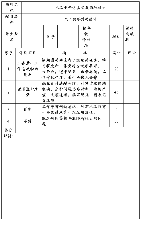
课程设计成绩评价表
指导教师: 年 7 月 25 日