结构力学
矩阵位移法上机实验报告


指导老师:
班 级:
姓 名:
学 号:
20##年10月29日
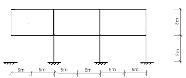
1.作图示刚架的 、
、 、
、 图,已知各杆截面均为矩形,柱截面宽0.5m,高0.5m, 梁截面宽0.4m,高0.5m,各杆E=3.65×10⁴ MPa。(10分)

(1)对杆件和结点编号,选定整体坐标系:
(2)输入数据并输出结果:
Input Data File Name: cyA.txt
Output File Name: cyA1.doc
*******************************************************************
* *
* 1 composite beam 2015.10.29 *
* *
*******************************************************************
The Input Data
The General Information
E NM NJ NS NLC
3.650E+07 15 13 12 1
The Information of Members
member start end A I
1 1 5 2.500000E-01 5.208333E-03
2 2 6 2.500000E-01 5.208333E-03
3 3 8 2.500000E-01 5.208333E-03
4 4 9 2.500000E-01 5.208333E-03
5 5 6 2.000000E-01 4.166667E-03
6 6 7 2.000000E-01 4.166667E-03
7 7 8 2.000000E-01 4.166667E-03
8 8 9 2.000000E-01 4.166667E-03
9 5 10 2.500000E-01 5.208333E-03
10 6 11 2.500000E-01 5.208333E-03
11 8 12 2.500000E-01 5.208333E-03
12 9 13 2.500000E-01 5.208333E-03
13 10 11 2.000000E-01 4.166667E-03
14 11 12 2.000000E-01 4.166667E-03
15 12 13 2.000000E-01 4.166667E-03
The Joint Coordinates
joint X Y
1 .000000 .000000
2 10.000000 .000000
3 20.000000 .000000
4 30.000000 .000000
5 .000000 8.000000
6 10.000000 8.000000
7 15.000000 8.000000
8 20.000000 8.000000
9 30.000000 8.000000
10 .000000 16.000000
11 10.000000 16.000000
12 20.000000 16.000000
13 30.000000 16.000000
The Information of Supports
IS VS
11 .000000
12 .000000
13 .000000
21 .000000
22 .000000
23 .000000
31 .000000
32 .000000
33 .000000
41 .000000
42 .000000
43 .000000
Loading Case 1
The Loadings at Joints
NLJ= 3
joint FX FY FM
5 .000000 .000000 -25.000000
7 .000000 -150.000000 -25.000000
13 -50.000000 .000000 -15.000000
The Loadings at Members
NLM= 7
member type VF DST
1 3 20.000000 8.000000
5 2 -150.000000 5.000000
8 4 -10.000000 10.000000
9 3 20.000000 8.000000
13 4 -10.000000 10.000000
14 4 -10.000000 10.000000
15 2 -150.000000 5.000000
The Results of Calculation
The Joint Displacements
joint u v rotation
1 2.925180E-21 -9.254433E-21 -1.748233E-20
2 5.407213E-21 -2.522309E-20 -2.400177E-20
3 6.086669E-21 -2.600218E-20 -2.574956E-20
4 4.580938E-21 -1.452029E-20 -2.171638E-20
5 1.629734E-02 -8.113475E-05 -2.433029E-03
6 1.613016E-02 -2.211340E-04 -9.985741E-04
7 1.607622E-02 -5.871796E-03 2.934707E-04
8 1.602228E-02 -2.279643E-04 -5.903658E-04
9 1.599214E-02 -1.273012E-04 -1.427690E-03
10 2.374694E-02 -1.237449E-04 8.226332E-05
11 2.362543E-02 -2.995206E-04 -2.706013E-04
12 2.351868E-02 -3.466569E-04 -1.052591E-03
13 2.341757E-02 -1.944612E-04 9.072026E-04
The Terminal Forces
member FN FS M
1 start 1 92.544329 109.251803 281.489985
end 5 -92.544329 50.748197 -47.475563
2 start 2 252.230950 54.072132 240.017662
end 6 -252.230950 -54.072132 192.559391
3 start 3 260.021817 60.866685 257.495616
end 8 -260.021817 -60.866685 229.437867
4 start 4 145.202905 45.809380 217.163757
end 9 -145.202905 -45.809380 149.311286
5 start 5 122.044419 43.942122 10.394944
end 6 -122.044419 106.057878 -320.973727
6 start 6 78.748386 56.763388 102.608772
end 7 -78.748386 -56.763388 181.208168
7 start 7 78.748386 -93.236612 -206.208168
end 8 -78.748386 93.236612 -259.974893
8 start 8 22.001170 31.401525 3.075273
end 9 -22.001170 68.598475 -189.060019
9 start 5 48.602207 71.296221 12.080619
end 10 -48.602207 88.703779 -81.710850
10 start 6 89.409683 10.776099 25.805565
end 11 -89.409683 -10.776099 60.403230
11 start 8 135.383680 4.119469 27.461752
end 12 -135.383680 -4.119469 5.494002
12 start 9 76.604430 23.808210 39.748733
end 13 -76.604430 -23.808210 150.716949
13 start 10 88.703779 48.602207 81.710850
end 11 -88.703779 51.397793 -95.688782
14 start 11 77.927679 38.011890 35.285552
end 12 -77.927679 61.988110 -155.166650
15 start 12 73.808210 73.395570 149.672648
end 13 -73.808210 76.604430 -165.716949
(3)作刚架的、、图:
弯矩M图:

剪力图:
轴力图
2、计算图示桁架各杆的轴力。已知A=400mm2,E=2.0×10⁵ MPa。(5分)

(1)对杆件和结点编号,选定整体坐标系:

(2)输入数据并输出结果:
Input Data File Name: cyB.txt
Output File Name: cyB2.doc
*******************************************************************
* *
* 2 composite beam 2015.10.29 *
* *
*******************************************************************
The Input Data
The General Information
E NM NJ NS NLC
2.000E+08 13 8 4 1
The Information of Members
member start end A I
1 1 2 4.000000E-04 1.000000E-20
2 2 3 4.000000E-04 1.000000E-20
3 3 4 4.000000E-04 1.000000E-20
4 4 5 4.000000E-04 1.000000E-20
5 6 7 4.000000E-04 1.000000E-20
6 7 8 4.000000E-04 1.000000E-20
7 1 6 4.000000E-04 1.000000E-20
8 2 6 4.000000E-04 1.000000E-20
9 2 7 4.000000E-04 1.000000E-20
10 3 7 4.000000E-04 1.000000E-20
11 7 4 4.000000E-04 1.000000E-20
12 4 8 4.000000E-04 1.000000E-20
13 8 5 4.000000E-04 1.000000E-20
The Joint Coordinates
joint X Y
1 .000000 .000000
2 5.000000 .000000
3 10.000000 .000000
4 15.000000 .000000
5 20.000000 .000000
6 5.000000 5.000000
7 10.000000 5.000000
8 15.000000 5.000000
The Information of Supports
IS VS
11 .000000
12 .000000
32 .000000
52 .000000
Loading Case 1
The Loadings at Joints
NLJ= 3
joint FX FY FM
6 25.000000 -50.000000 .000000
7 .000000 -50.000000 .000000
8 .000000 -50.000000 .000000
The Loadings at Members
NLM= 0
The Results of Calculation
The Joint Displacements
joint u v rotation
1 2.500000E-21 -2.045569E-21 -2.761560E-03
2 2.840980E-03 -9.355533E-03 7.659292E-05
3 3.835441E-03 -9.658863E-21 -2.751700E-05
4 4.829902E-03 -8.964908E-03 -2.560604E-04
5 6.889633E-03 -3.295569E-21 2.521479E-03
6 7.585964E-03 -1.120205E-02 -3.491674E-04
7 4.744983E-03 -6.036789E-03 3.321934E-05
8 2.685253E-03 -1.003018E-02 6.469057E-05
The Terminal Forces
member FN FS M
1 start 1 -45.455687 .000000 .000000
end 2 45.455687 .000000 .000000
2 start 2 -15.911373 .000000 .000000
end 3 15.911373 .000000 .000000
3 start 3 -15.911373 .000000 .000000
end 4 15.911373 .000000 .000000
4 start 4 -32.955687 .000000 .000000
end 5 32.955687 .000000 .000000
5 start 6 45.455687 .000000 .000000
end 7 -45.455687 .000000 .000000
6 start 7 32.955687 .000000 .000000
end 8 -32.955687 .000000 .000000
7 start 1 28.928709 .000000 .000000
end 6 -28.928709 .000000 .000000
8 start 2 29.544313 .000000 .000000
end 6 -29.544313 .000000 .000000
9 start 2 -41.781969 .000000 .000000
end 7 41.781969 .000000 .000000
10 start 3 96.588627 .000000 .000000
end 7 -96.588627 .000000 .000000
11 start 7 -24.104299 .000000 .000000
end 4 24.104299 .000000 .000000
12 start 4 17.044313 .000000 .000000
end 8 -17.044313 .000000 .000000
13 start 8 46.606379 .000000 .000000
end 5 -46.606379 .000000 .000000
(3)做轴力图:

3.作图示连续梁的、图,已知各杆截面均为矩形,截面宽0.35m,高0.5m,各杆E=3.45×10⁴MPa。(5分)

(1)对杆件和结点编号,选定整体坐标系:

(2)输入数据并输出结果:
Input Data File Name: cyC.txt
Output File Name: cyC3.doc
*******************************************************************
* *
* 3 composite beam 2015.10.29 *
* *
*******************************************************************
The Input Data
The General Information
E NM NJ NS NLC
3.450E+07 4 5 6 1
The Information of Members
member start end A I
1 1 2 1.750000E-01 3.645833E-03
2 2 3 1.750000E-01 3.645833E-03
3 3 4 1.750000E-01 3.645833E-03
4 4 5 1.750000E-01 3.645833E-03
The Joint Coordinates
joint X Y
1 .000000 .000000
2 3.000000 .000000
3 5.000000 .000000
4 7.000000 .000000
5 10.000000 .000000
The Information of Supports
IS VS
11 .000000
12 .000000
13 .000000
22 .000000
42 .000000
52 .000000
Loading Case 1
The Loadings at Joints
NLJ= 2
joint FX FY FM
3 .000000 -120.000000 50.000000
4 .000000 .000000 -25.000000
The Loadings at Members
NLM= 2
member type VF DST
1 4 -10.000000 3.000000
4 2 -120.000000 1.500000
The Results of Calculation
The Joint Displacements
joint u v rotation
1 0.000000E+00 1.622642E-21 1.622642E-21
2 0.000000E+00 -7.969340E-21 -1.935076E-04
3 0.000000E+00 -3.495137E-04 1.803821E-04
4 0.000000E+00 -7.356132E-21 -1.305051E-04
5 0.000000E+00 1.702830E-21 3.335756E-04
The Terminal Forces
member FN FS M
1 start 1 .000000 -1.226415 -8.726415
end 2 .000000 31.226415 -39.952830
2 start 2 .000000 63.466981 39.952830
end 3 .000000 -63.466981 86.981132
3 start 3 .000000 -56.533019 -36.981132
end 4 .000000 56.533019 -76.084906
4 start 4 .000000 77.028302 51.084906
end 5 .000000 42.971698 .000000
(3)做弯矩图、剪力图:
做弯矩M图

做剪力FS图
