IP通信基础实验报告
VLAN间路由实验
一、 实验目的
掌握三层交换机静态路由的配置方法
二、 实验内容(仿真程序‘静态路由switcher.pkt’)
三层交换机静态路由的配置
三、 实验设备
三层交换机 3台
PC机 2台
交叉网线 2条
直通网线 2条
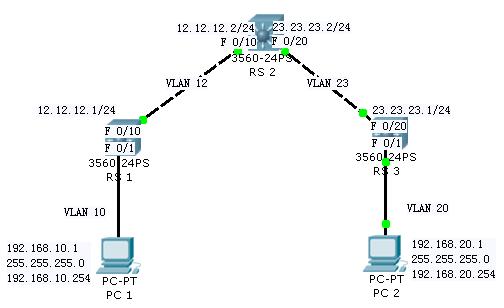
四、 实验拓扑图
五、 配置步骤
====底层配置
RS1
Switch>enable
Switch#configure terminal
Enter configuration commands, one per line. End with CNTL/Z.
Switch(config)#hostname RS1
RS1(config)#vlan 10
RS1(config-vlan)#exit
RS1(config)#vlan 12
RS1(config-vlan)#exit
RS1(config)#interface fastEthernet 0/1
RS1(config-if)#no shutdown
RS1(config-if)#switchport mode access
RS1(config-if)#switchport access vlan 10
RS1(config-if)#exit
RS1(config)#interface vlan 10
%LINK-5-CHANGED: Interface Vlan10, changed state to up
%LINEPROTO-5-UPDOWN: Line protocol on Interface Vlan10, changed state to up
RS1(config-if)#ip address 192.168.10.254 255.255.255.0
RS1(config-if)#exit
RS1(config)#interface fastEthernet 0/10
RS1(config-if)#no shutdown
RS1(config-if)#switchport mode access
RS1(config-if)#switchport access vlan 12
RS1(config-if)#exit
RS1(config)#interface vlan 12
%LINK-5-CHANGED: Interface Vlan12, changed state to up
%LINEPROTO-5-UPDOWN: Line protocol on Interface Vlan12, changed state to up
RS1(config-if)#no shutdown
RS1(config-if)#ip address 12.12.12.1 255.255.255.0
RS1(config-if)#exit
RS1(config)#
RS2==============================================================
Switch>enable
Switch#configure terminal
Enter configuration commands, one per line. End with CNTL/Z.
Switch(config)#hostname RS2
RS2(config)#vlan 12
RS2(config-vlan)#exit
RS2(config)#vlan 23
RS2(config-vlan)#exit
RS2(config)#interface fastEthernet 0/10
RS2(config-if)#no shutdown
RS2(config-if)#switchport mode access
RS2(config-if)#switchport access vlan 12
RS2(config-if)#exit
RS2(config)#interface vlan12
%LINK-5-CHANGED: Interface Vlan12, changed state to up
%LINEPROTO-5-UPDOWN: Line protocol on Interface Vlan12, changed state to up
RS2(config-if)#no shutdown
RS2(config-if)#ip address 12.12.12.2 255.255.255.0
RS2(config-if)#exit
RS2(config)#interface fastEthernet 0/20
RS2(config-if)#no shutdown
RS2(config-if)#switchport mode access
RS2(config-if)#switchport access vlan 23
RS2(config-if)#exit
RS2(config)#interface vlan23
RS2(config-if)#
%LINK-5-CHANGED: Interface Vlan23, changed state to up
%LINEPROTO-5-UPDOWN: Line protocol on Interface Vlan23, changed state to up
RS2(config-if)#no shutdown
RS2(config-if)#ip address 23.23.23.2 255.255.255.0
RS2(config-if)#exit
RS2(config)#
RS3=================================================================
Switch>enable
Switch#configure terminal
Enter configuration commands, one per line. End with CNTL/Z.
Switch(config)#hostname RS3
RS3(config)#vlan 23
RS3(config-vlan)#exit
RS3(config)#vlan 20
RS3(config-vlan)#exit
RS3(config)#interface fastEthernet 0/20
RS3(config-if)#no shutdown
RS3(config-if)#switchport mode access
RS3(config-if)#switchport access vlan 23
RS3(config-if)#exit
RS3(config)#interface vlan 23
%LINK-5-CHANGED: Interface Vlan23, changed state to up
%LINEPROTO-5-UPDOWN: Line protocol on Interface Vlan23, changed state to up
RS3(config-if)#no shutdown
RS3(config-if)#ip address 23.23.23.1 255.255.255.0
RS3(config-if)#exit
RS3(config)#interface fastEthernet 0/1
RS3(config-if)#no shutdown
RS3(config-if)#switchport mode access
RS3(config-if)#switchport access vlan 20
RS3(config-if)#exit
RS3(config)#interface vlan20
%LINK-5-CHANGED: Interface Vlan20, changed state to up
%LINEPROTO-5-UPDOWN: Line protocol on Interface Vlan20, changed state to up
RS3(config-if)#no shutdown
RS3(config-if)#ip address 192.168.20.254 255.255.255.0
RS3(config-if)#exit
RS3(config)#
====静态路由配置
RS1
RS1(config)#ip route 192.168.20.0 255.255.255.0 12.12.12.2
RS1(config)#ip route 23.23.23.0 255.255.255.0 12.12.12.2
RS2
RS2(config)#ip route 192.168.20.0 255.255.255.0 23.23.23.1
RS2(config)#ip route 192.168.10.0 255.255.255.0 12.12.12.1
RS3
RS3(config)#ip route 192.168.10.0 255.255.255.0 23.23.23.2
RS3(config)#ip route 12.12.12.0 255.255.255.0 23.23.23.2
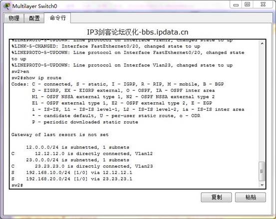
六、 验证方法及验证结果
sw2#show ip route %可以查看路由表
验证结果如下:
七、 实验结论
路由器能够通过配置,学习到网络的路由信息,创建路由表。同样,三层交换机也具有这样的功能。三层交换机可以通过创建VLAN的方式,对其端口进行IP配置,然后通过路由配置,得到网络的路由表,实现VLAN间路由。
第二篇:跨交换机实现VLAN实验报告
计算机网络实验报告
——跨交换机实现VLAN
实验目的
跨交换机实现VLAN的划分与配置。
一、实验器材
? 两台Switch2950交换机。
? 四台PC机,其中一台装有超级终端仿真软件
? 一根console控制台电缆,直通双绞线若干,交叉双绞线若干。
二、实验任务
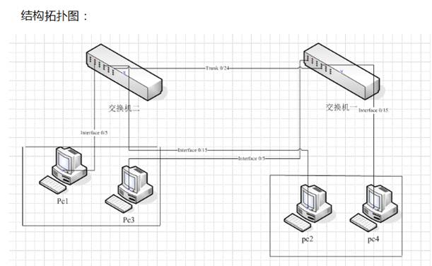
本实验实验拓扑图如下图,根据该网络结构所需网段,进行ip地址规划,需要完成的工作如下:
 1、实验设备的选择与调试。
2、根据实验拓扑图,连接端口。
3、配置ip地址,并配置静态路由。
4、设置pc机IP地址及默认网关,并通过ping命令检查。
三、实验原理
(1) 交换机基础配置
Interface range fa0/1-12 定义端口范围
Switchport access vlan 将所定义的端口划分到vlanX
(2) 常用命令
1)改变状态命令
进入特权命令状态 enable
退出特权命令状态 disable
进入设置对话状态 setup
进入全局设置状态 config terminal
退出全局设置状态 end
进入端口设置状态 interface type slot/number
进入子端口设状态 interface type numeber.subinterface[point-to-point|multipoint]
进入线路设置状态 line type slot/number
进入路由设置状态 router protocol
退出局部设置状态 exit
2.)显示命令
查看版本及引导信息 show version
查看运行设置 show running-config //简写 show run 特权模式
查看开机设置 show startup-config
显示端口信息 show controllers type slot/number
3)拷贝命令
将配置保存到NVRAM:copy running-config startup-config。
4.)网络命令
登录远程主机 telnet hostname|IP_address
网络侦测 ping hostname|IP_address
5)基本设置命令
全局设置 config terminal //简写 config t //进入全局模式
设置访问用户及密码 username username password password
设置特权密码 enable secret password 查询密码 设置暗码
修改密码 //enable password + 密码 修改密码
四、实验步骤及原程程序
4.1 实验设备选择与调试:
交换机选择:本实验选择Cisco Packet Tracer 5.0中提供的2950-24为实验用交换机。
PC选择:本实验选择Cisco Packet Tracer 5.0提供的普通PC机进行实验。
4.2 根据实验拓扑图连接计算机。
如下图所示根据拓扑图连接各实验设备。
4.3 设置交换机
在交换机1上创建两个VLAN,分别为VLAN2、VLAN3,并将交换机1的前面12个端口划分到VLAN2中,将交换机1的后12个端口划分到VLAN3中。同样在交换机2创建两个VLAN,分别为VLAN2与VLAN3,并将前12个端口划分到VLAN2中,将后12个端口划分到VLAN3中。具体的操作步骤如下:
具体配置命令如下:
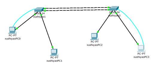
交换机1的配置:
Switch1>enable
Switch1#config t
Switch(Config)# hostname xushiyao1
xushiyao1>enable
xushiyao1#vlan database
% Warning: It is recommended to configure VLAN from config mode,
as VLAN database mode is being deprecated. Please consult user
documentation for configuring VTP/VLAN in config mode.
xushiyao1(vlan)#vlan 2
VLAN 2 modified:
xushiyao1(vlan)#vlan 2 name vlan2
VLAN 2 modified:
Name: vlan2
xushiyao1(vlan)#vlan 3
VLAN 3 modified:
xushiyao1(vlan)#vlan 3 name vlan3
VLAN 3 modified:
Name: vlan3
xushiyao1(vlan)#exit
APPLY completed.
Exiting....
xushiyao1#
xushiyao1#config t
Enter configuration commands, one per line. End with CNTL/Z.
xushiyao1(config)#interface range fa0/1-12
xushiyao1(config-if-range)#switchport access vlan 2
xushiyao1(config-if-range)#no shut
xushiyao1(config-if-range)#exit
xushiyao1(config)#interface range fa0/13-24
xushiyao1(config-if-range)#switchport access vlan 3
xushiyao1(config-if-range)#no shut
xushiyao1(config-if-range)#exit
xushiyao1(config)#exit
xushiyao1#
%SYS-5-CONFIG_I: Configured from console by console
xushiyao1#copy run start
Destination filename [startup-config]?
Building configuration...
[OK]
xushiyao1#
交换机2的设置:
交换机2设置同交换机1,此处便不再重复
五、PC机IP地址设置及检验
PC 上的配置为:
xushiyao PC0:IP:192.168.0.2 子网掩码:255.255.255.0
xushiyaoPC1:IP:192.168.0.3 子网掩码:255.255.255.0
xushiyaoPC2:IP:192.168.0.4 子网掩码:255.255.255.0
xushiyaoPC3:IP:192.168.0.5 子网掩码:255.255.255.0
全局通信测试:
xushiyaoPC0:ping 192.168.0.2(检验本机ip协议)
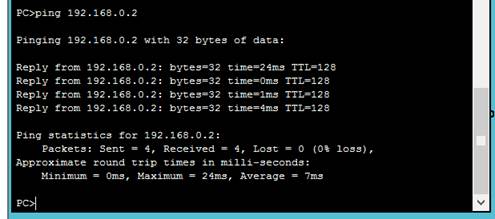
结论:本机ip协议运作正常。
xushiyaoPC0:ping 192.168.0.3 (检验同交换机不同VLAN上的联通性)
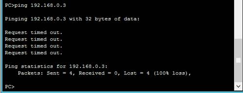
结果:同交换机不同VLAN间不能通信。
xushiyaoPC0:ping 192.168.0.4 (检验同交换机同种VLAN上的联通性)
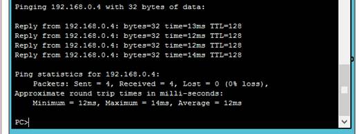
实验结论:不同交换机同种VLAN间实现了联通通信。
xushiyaoPC0:ping 192.168.0.5 (检验不同交换机不同VLAN上的联通性)

实验结论:不同交换机不同种VLAN间不能通信。
综上所述,通过交换机实现VLAN控制可以达到目标VLAN的划分与配置。
六、实验结论及分析
通过实验顺利使用交换机控制了VLAN的划分与配置,实现了不同交换机下同VLAN计算机间的通信及控制,即跨交换机实现VLAN。同时控制了不属于一VLAN的计算机无法通信。实验成功。