静态路由配置实验报告
10网络 王志龙 2010304020104
一.实验目的:
掌握路由器的基本使用及配置静态路由。
二.实验内容:
1. 给各路由器命名。
2. 给路由器及PC配置ip地址。
3. 给各路由器配置路由。
4. 测试路由是否连通。
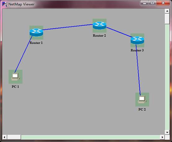
三.实验环境及网络结构拓扑图:
1. 环境:window7 思科模拟路由器。
2. 拓扑图:
四.实验过程:
1. 把设计好的网络拓扑图装载入思科模拟路由软件。
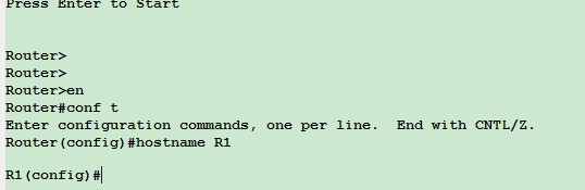
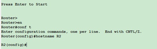
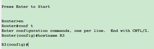
2. 给各路由器命名为R1,R2,R3。
R1:
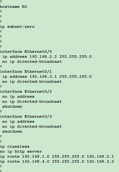
R2:
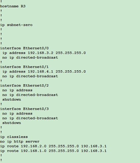
R3:
3. 按照下表配置R1 的Ip和路由。
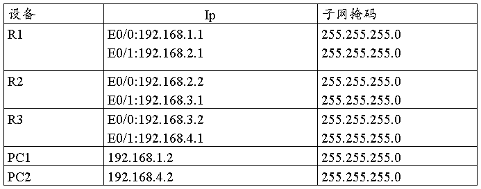
R1: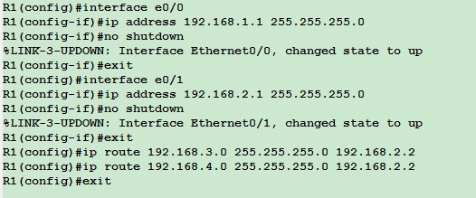
各路由器配好如下:
R2:
R3:
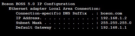
Pc1:
Pc2: 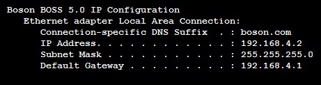
4. ping测试:
Pc1 ping pc2:
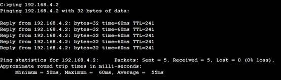
结果为通
Pc2 ping pc1:
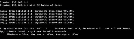
结果为通
五.试验总结:
1. 在配置ip地址时要注意进入的端口,ip地址和端口要按预先设计好的一一对应.
2. 在配置路由时应注意弄清楚进入目的网络的下一跳端口IP。
3. 实验中配置好后可以使用show runing-config 命令来检查各端口是否配错.
第二篇:《计算机网络》实验六 静态路由配置 实验报告
实验报告六
班级:07东方信息 姓名: 学号:
实验时间:10年5月17日 机房:9#205 组号: 机号:A
一、实验题目 静态路由配置
二、实验设备
CISCO路由器、专用电缆、网线、CONSOLE线、PC机
三、实验内容
1了解路由器的功能
2在CISCO路由器上设置和验证静态路由
3配置缺省路由
四、原理
实现网络的互连互通,从而实现信息的共享和传输。
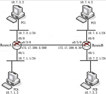
静态路由实验网络拓扑结构图:
五、实际步骤
步骤1:初始化设置
(1)按照图4-1的网络拓扑结构,连接好PC与路由器的网线、PC与路由器Console端口的调试电缆、路由器与路由器之间的V.35电缆。
(2)按照图4-1要求,在PC1、PC2计算机中设置好IP地址、子网掩码、默认网关。然后利用Ping命令测试两台PC机之间的连通性。模拟器也按以上配置。
(3)在PC机上启动“超级终端”。
步骤2:路由器 Route A 的基础配置
7-A#show run
Building configuration...
Current configuration : 826 bytes
!
version 12.3
service timestamps debug datetime msec
service timestamps log datetime msec
no service password-encryption
!
hostname 7-A
!
boot-start-marker
boot-end-marker
!
enable password cisco
!
no network-clock-participate aim 0
no network-clock-participate aim 1
no aaa new-model
ip subnet-zero
!
!
ip cef
!
!
no ftp-server write-enable
!
!
!
!
interface FastEthernet0/0
ip address 10.7.3.1 255.255.255.0
duplex auto
speed auto
!
interface FastEthernet0/1
ip address 10.7.1.1 255.255.255.0
duplex auto
speed auto
!
interface Serial0/3/0
ip address 172.17.200.5 255.255.255.252
no fair-queue
!
interface Serial0/3/1
no ip address
shutdown
clockrate 2000000
!
ip classless
ip http server
!
!
!
control-plane
!
!
line con 0
line aux 0
line vty 0 4
password cisco
login
!
scheduler allocate 20000 1000
!
End
步骤3:路由器 Route B 的基础配置
7-B#show run
Building configuration...
Current configuration : 868 bytes
!
version 12.3
service timestamps debug datetime msec
service timestamps log datetime msec
no service password-encryption
!
hostname 7-B
!
boot-start-marker
boot-end-marker
!
enable password cisco
!
no network-clock-participate aim 0
no network-clock-participate aim 1
no aaa new-model
ip subnet-zero
!
!
ip cef
!
!
no ftp-server write-enable
!
!
!
!
interface FastEthernet0/0
ip address 10.7.3.1 255.255.255.0
shutdown
duplex auto
speed auto
!
interface FastEthernet0/1
ip address 10.7.2.1 255.255.255.0
duplex auto
speed auto
!
interface Serial0/3/0
ip address 172.17.200.6 255.255.255.252
no fair-queue
clockrate 128000
!
interface Serial0/3/1
bandwidth 64
no ip address
shutdown
clockrate 2000000
!
ip classless
ip http server
!
!
!
control-plane
!
!
line con 0
line aux 0
line vty 0 4
password cisco
login
!
scheduler allocate 20000 1000
!
end
步骤4:在 Route A 上配置静态路由
7-A(config)#ip route 10.7.2.0 255.255.255.0 172.17.200.6
7-A(config)#10.7.4.0 255.255.255.0 172.17.200.6
步骤5:检查9-A上的路由表
7-A#show ip route
Codes: C - connected, S - static, R - RIP, M - mobile, B - BGP
D - EIGRP, EX - EIGRP external, O - OSPF, IA - OSPF inter area
N1 - OSPF NSSA external type 1, N2 - OSPF NSSA external type 2
E1 - OSPF external type 1, E2 - OSPF external type 2
i - IS-IS, su - IS-IS summary, L1 - IS-IS level-1, L2 - IS-IS level-2
ia - IS-IS inter area, * - candidate default, U - per-user static route
o - ODR, P - periodic downloaded static route
Gateway of last resort is not set
172.17.0.0/30 is subnetted, 1 subnets
C 172.17.200.4 is directly connected, Serial0/3/0
10.0.0.0/24 is subnetted, 4 subnets
S 10.7.4.0 [1/0] via 172.17.200.6
C 10.7.1.0 is directly connected, FastEthernet0/1
C 10.7.3.0 is directly connected, FastEthernet0/0
S 10.7.2.0 [1/0] via 172.17.200.6
步骤6:Ping 7-B的FastEthernet端口的地址。
7-A#Ping 10.7.2.1
Type escape sequence to abort.
Sending 5, 100-byte ICMP Echos to 10.7.2.1, timeout is 2 seconds:
!!!!!
Success rate is 100 percent (5/5), round-trip min/avg/max = 12/14/16 ms
7-A#Ping 10.7.4.1
Type escape sequence to abort.
Sending 5, 100-byte ICMP Echos to 10.7.4.1, timeout is 2 seconds:
!!!!!
Success rate is 100 percent (5/5), round-trip min/avg/max = 12/14/16 ms
步骤7:在9-B上配置缺省路由
7-B(config)#ip route 0.0.0.0 0.0.0.0 172.17.200.5
步骤8:在9-B上查看路由表
7-B#show ip route
Codes: C - connected, S - static, R - RIP, M - mobile, B - BGP
D - EIGRP, EX - EIGRP external, O - OSPF, IA - OSPF inter area
N1 - OSPF NSSA external type 1, N2 - OSPF NSSA external type 2
E1 - OSPF external type 1, E2 - OSPF external type 2
i - IS-IS, su - IS-IS summary, L1 - IS-IS level-1, L2 - IS-IS level-2
ia - IS-IS inter area, * - candidate default, U - per-user static route
o - ODR, P - periodic downloaded static route
Gateway of last resort is 172.17.200.5 to network 0.0.0.0
172.17.0.0/30 is subnetted, 1 subnets
C 172.17.200.4 is directly connected, Serial0/3/0
10.0.0.0/24 is subnetted, 2 subnets
C 10.7.4.0 is directly connected, FastEthernet0/0
C 10.7.2.0 is directly connected, FastEthernet0/1
S* 0.0.0.0/0 [1/0] via 172.17.200.5
步骤9:Ping 7-A的FastEthernet端口的地址
7-B#ping 10.7.1.1
Type escape sequence to abort.
Sending 5, 100-byte ICMP Echos to 10.7.1.1, timeout is 2 seconds:
!!!!!
Success rate is 100 percent (5/5), round-trip min/avg/max = 12/14/16 ms
7-B#ping 10.7.3.1
Type escape sequence to abort.
Sending 5, 100-byte ICMP Echos to 10.7.3.1, timeout is 2 seconds:
!!!!!
Success rate is 100 percent (5/5), round-trip min/avg/max = 12/13/16 ms
步骤10. 在 Route B 上删除缺省路由配置,配置静态路由
7-B#conf t
Enter configuration commands, one per line. End with CNTL/Z.
7-B(config)# no ip route 0.0.0.0 0.0.0.0 172.17.200.5
7-B(config)#ip route 10.7.1.0 255.255.255.0 172.17.200.5
7-B(config)#ip route 10.7.3.0 255.255.255.0 172.17.200.5
步骤11. 查看路由表
7-B#show ip route
Codes: C - connected, S - static, R - RIP, M - mobile, B - BGP
D - EIGRP, EX - EIGRP external, O - OSPF, IA - OSPF inter area
N1 - OSPF NSSA external type 1, N2 - OSPF NSSA external type 2
E1 - OSPF external type 1, E2 - OSPF external type 2
i - IS-IS, su - IS-IS summary, L1 - IS-IS level-1, L2 - IS-IS level-2
ia - IS-IS inter area, * - candidate default, U - per-user static route
o - ODR, P - periodic downloaded static route
Gateway of last resort is 172.17.200.5 to network 0.0.0.0
172.17.0.0/30 is subnetted, 1 subnets
C 172.17.200.4 is directly connected, Serial0/3/0
10.0.0.0/24 is subnetted, 2 subnets
C 10.7.4.0 is directly connected, FastEthernet0/0
C 10.7.2.0 is directly connected, FastEthernet0/1
S* 0.0.0.0/0 [1/0] via 172.17.200.5
步骤12. 测试网络的连通性
7-B(config)#ip route 10.7.1.0 255.255.255.0 172.17.200.5
7-B(config)#ip route 10.7.3.0 255.255.255.0 172.17.200.5
7-B#ping 10.7.1.1
Type escape sequence to abort.
Sending 5, 100-byte ICMP Echos to 10.7.1.1, timeout is 2 seconds:
!!!!!
Success rate is 100 percent (5/5), round-trip min/avg/max = 12/15/16 ms
7-B#ping 10.7.3.1
Type escape sequence to abort.
Sending 5, 100-byte ICMP Echos to 10.7.3.1, timeout is 2 seconds:
!!!!!
Success rate is 100 percent (5/5), round-trip min/avg/max = 12/15/16 ms
7-A#Ping 10.7.2.1
Type escape sequence to abort.
Sending 5, 100-byte ICMP Echos to 10.7.2.1, timeout is 2 seconds:
!!!!!
Success rate is 100 percent (5/5), round-trip min/avg/max = 12/14/16 ms
7-A#Ping 10.7.4.1
Type escape sequence to abort.
Sending 5, 100-byte ICMP Echos to 10.7.4.1, timeout is 2 seconds:
!!!!!
Success rate is 100 percent (5/5), round-trip min/avg/max = 12/15/16 ms
六、成果与总结
此次试验在上次“IP地址分配”的试验之后,通过对两次的实验结果的连通状态的比较,从原理上分析,学习了两次实验的差别。通过此次试验进一步的学习了计算机网络的知识