实验一、半加器与全加器的电路图实现
(一) 半加器
1、半加器的电路图——见图1
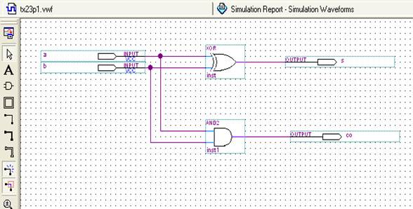
图1——半加器的电路图
2、半加器仿真波形图——见图2

图2——半加器仿真波形图
3、仿真图简析:如图2,为半加器仿真波形图。对应a,b输入波形,得到的c为进位,s为和。如a=1,b=0,c=0,s=1.
4、半加器的VHDL语言为:
library ieee;
use ieee.std_logic_1164.all;
entity tx23p31 is
port (a,b:in std_logic;
co,so:out std_logic);
end entity tx23p31;
architecture a of tx23p31 is
begin
so<= a xor b;
co<= a and b;
end;
(二) 全加器
1、全加器的电路图——见图3
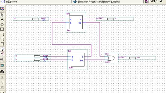
图3——全加器的电路图
2、全加器的VHDL语言
library ieee;
use ieee.std_logic_1164.all;
entity tx23p3 is
port (ain,bin,cin:in std_logic;
cout,sum:out std_logic);
end entity tx23p3;
architecture a of tx23p3 is
component tx23p31
port(a,b:in std_logic;
co,so: out std_logic);
end component;
signal d,e,f:std_logic;
begin
u1:tx23p31 port map (a=>ain,b=>bin,co=>d,so=>e);
u2:tx23p31 port map (a=>e,b=>cin,co=>f,so=>sum);
cout<=d or f;
end;
3、全加器的RTL viewer:见图4
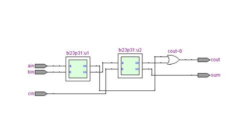
图4——全加器的RTL viewer
实验二、函数发生器
1、电路图——见图5
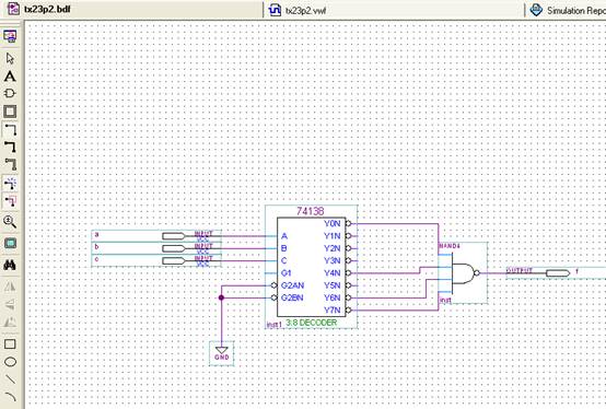
图5——函数发生器的实验电路图
2、函数发生器的仿真波形图——见图6

图6——函数发生器的仿真波形图
3、波形图仿真分析:如上图,当a,b,c的取值为0,4,6,7时,f=1;其他时刻,f=0。如第一列波形,a=0,b=0,c=0,此时f=1.
实验三、四选一数据选择器
library ieee;
use ieee.std_logic_1164.all;
entity tx23w1 is
port(a:in std_logic_vector(1 downto 0);
d:in std_logic_vector(3 downto 0);
y:out std_logic);
end tx23w1;
architecture mux4 of tx23w1 is
begin
process(a,d)
begin
case a is
when "00" => y<=d(0);
when "01" => y<=d(1);
when "10" => y<=d(2);
when "11" => y<=d(3);
when others=>y<='0';
end case;
end process;
end mux4;
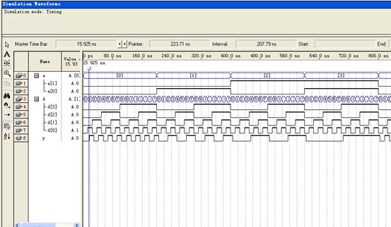
图7——四选一数据选择器波形图
实验四、裁判器
library ieee;
use ieee.std_logic_1164.all;
entity tx23w2 is
port(a:in std_logic_vector(2 downto 0);
y:out std_logic_vector(1 downto 0));
end tx23w2;
architecture mux8 of tx23w2 is
begin
process(a)
begin
case a is
when "000" => y<= "00";
when "001" => y<= "00";
when "010" => y<= "00";
when "011" => y<= "10";
when "100" => y<= "10";
when "101" => y<= "11";
when "110" => y<= "11";
when "111" => y<= "11";
when others=> y<="00";
end case;
end process;
end mux8;
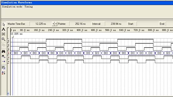
图8——裁判表决器
实验五、50M分频器
library ieee;
use ieee.std_logic_1164.all;
use ieee.std_logic_unsigned.all;
entity tx23w3 is
port ( clk: in std_logic;
clear: in std_logic;
clk_out:out std_logic);
end tx23w3;
architecture a of tx23w3 is
signal tmp:integer range 0 to 50000000;
begin
p1:process (clear,clk)
begin
if clear='0' then
tmp<=0;
elsif clk'event and clk='1' then
if tmp=49999999 then
tmp<=0;
else
tmp<=tmp+1;
end if;
end if ;
end process p1;
p2: process (clk,tmp)
begin
if (clk'event and clk='1') then
if tmp>=25000000 then
clk_out<='1';
else clk_out<='0';
end if ;
end if;
end process p2;
end a;
实验六、七段荧光屏数码显示学号
library ieee;
use ieee.std_logic_1164.all;
use ieee.std_logic_unsigned.all;
entitiy tx23h1 is
port(
clk:in std_logic;
seg:out std_logic_vector(6 downto 0);
cat:out std_logic_vector (5 downto 0));
end tx23h1;
architecture a of tx23h1 is
signal tmp: integer range 0 to 5;
signal clk_tmp: integer range 0 to 100000;
signal clk_out: std_logic;
signal move:
begin
p1:process(clk)
begin
if (clk'event and clk='1') then
if clk_tmp=49999 then
clk_tmp<=0;
clk_out<=not clk_out;
else clk_tmp<=clk_tmp+1;
end if;
end if ;
end process p1; //进程一:分频系数为100000的分频器
p2:process(clk_out)
begin
if (clk_out'event and clk_out='1') then
if tmp=5 then
tmp<=0;
else tmp<=tmp+1;
end if;
end if;
end process p2; //进程二:模制为六的计数器
p3:process(tmp)
begin
case tmp is
when 0=>seg<="0110000";
when 1=>seg<="1101101";
when 2=>seg<="1111110";
when 3=>seg<="1111111";
when 4=>seg<="1101101";
when 5=>seg<="1111001";
end case;
end process p3; //进程三:不同计数器的计数值时的显示数字,从0~5为:120823
p4:process(tmp)
begin
case tmp is
when 0=>cat<="011111";
when 1=>cat<="101111";
when 2=>cat<="110111";
when 3=>cat<="111011";
when 4=>cat<="111101";
when 5=>cat<="111110"; //进程四:选择输出的荧光屏数码管
end case;
end process p4;
end a;
实验七、实现自己学号滚动的七段荧光屏数码显示
library ieee;
use ieee.std_logic_1164.all;
use ieee.std_logic_unsigned.all;
entity tx23h2 is
port(clk : in std_logic;
seg : out std_logic_vector(6 downto 0);
cat:out std_logic_vector(5 downto 0));
end tx23h2;
architecture a of tx23h2 is
signal cnt1 : integer range 0 to 49999;
signal cnt2 : integer range 0 to 499;
signal clk_tmp1 : std_logic;
signal clk_tmp2 : std_logic;
signal q_tmp1: integer range 0 to 5;
signal q_tmp2: integer range 0 to 5;
begin
p1:process(clk)
begin
if (clk'event and clk ='1') then
if cnt1=49999 then
cnt1<=0;
clk_tmp1<= not clk_tmp1;
else
cnt1<=cnt1+1;
end if;
end if;
end process p1; //分频系数为100000的分频器
p2:process(clk_tmp1)
begin
if (clk_tmp1'event and clk_tmp1='1') then
if cnt2=499then
cnt2<=0;
clk_tmp2<= not clk_tmp2;
else
cnt2<=cnt2+1;
end if;
end if;
end process p2; //分频系数为1000的分频器,使最后的滚动时间变为2秒
p3:process(clk_tmp1)
begin
if(clk_tmp1'event and clk_tmp1='1')then
if q_tmp1=5 then
q_tmp1<=0;
else
q_tmp1<=q_tmp1+1;
end if;
end if;
end process p3; //计数器,模制为6,第一个时钟的时钟沿有效
p4:process(clk_tmp2)
begin
if(clk_tmp2'event and clk_tmp2='1')then
if q_tmp2=5 then
q_tmp2<=0;
else
q_tmp2<=q_tmp2+1;
end if;
end if;
end process p4; //计数器,模制为6,第二个时钟的时钟沿有效
p5:process(q_tmp1)
begin
case q_tmp1 is
when 0 => seg <="0110000"; //通过计数器1的值选择要输出的信息,为120823
when 1 => seg <="1101101";
when 2 => seg <="1111110";
when 3 => seg <="1111111";
when 4 => seg <="1101101";
when 5 => seg <="1111001";
when others => seg <="1111111";
end case;
end process p5;
p6:process(q_tmp1,q_tmp2)
begin
case (q_tmp1+q_tmp2) rem 6 is //q_tmp1 +q_tmp2为两个计数器的计数值之和,模 when 0 => cat <="011111"; //六之后的数值进行循环,用余数选择荧光数码管
when 1 => cat <="101111"; //实现学号的滚动输出,这一步是本电路的核心;
when 2 => cat <="110111";
when 3 => cat <="111011";
when 4 => cat <="111101";
when 5 => cat <="111110";
when others => cat <="000000";
end case;
end process p6;
end a;
(注:为了是波形显示有序清晰,重新修改了代码、重新设置了分频器的系数等参数,将显示在数码管上的数据改成了012345)
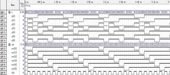
图9——七段荧光屏数码显示
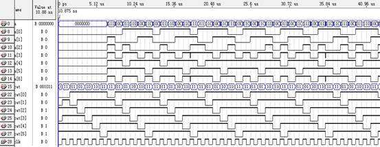
图10——七段荧光屏数码滚动显示波形图
实验七、发光二极管走马灯电路设计与实现——状态机的设计
LIBRARY IEEE;
USE IEEE.STD_LOGIC_1164.ALL;
USE IEEE.STD_LOGIC_UNSIGNED.ALL;
ENTITY tx23h3 IS
PORT(
clk:IN STD_LOGIC;
clear:IN STD_LOGIC;
swich:IN STD_LOGIC;
q_out:OUT STD_LOGIC_VECTOR(7 DOWNTO 0));
END tx23h3;
ARCHITECTURE a OF tx23h3 IS
SIGNAL tmp:INTEGER RANGE 0 TO 7; // 定义结构体内部信号为从0-7的整型
SIGNAL e:STD_LOGIC;
COMPONENT div50m //加入50分频
PORT(clk_in:IN STD_LOGIC;
clk_out:OUT STD_LOGIC);
END COMPONENT;
BEGIN
u1:div50m PORT MAP(clk_in=>clk,clk_out=>e);
p1:PROCESS(e)
BEGIN
IF e'event AND e='1' THEN //检测到时钟的上升沿
IF tmp=7 THEN
tmp<=0;
ELSE
tmp<=tmp+1; // 信号依次改变
END IF;
END IF;
END PROCESS p1;
//进程1
p2:PROCESS(clear,tmp)
BEGIN
IF(clear='0')THEN //clear=0时,置零
q_out<="00000000";
ELSE
CASE tmp IS // case语句控制输出的值随tmp的值依次变化
IF(swich='1')THEN //clear=1,swich=1时,完成单点移动模式
WHEN 0=>q_out<="00000001";
WHEN 1=>q_out<="00000010";
WHEN 2=>q_out<="00000100";
WHEN 3=>q_out<="00001000";
WHEN 4=>q_out<="00010000";
WHEN 5=>q_out<="00100000";
WHEN 6=>q_out<="01000000";
WHEN 7=>q_out<="10000000";
END case;
ELSE
CASE tmp IS //clear=1,swich=0时,完成幕布模式
WHEN 0=>q_out<="00011000";
WHEN 1=>q_out<="00111100";
WHEN 2=>q_out<="01111110";
WHEN 3=>q_out<="11111111";
WHEN 4=>q_out<="01111110";
WHEN 5=>q_out<="00111100";
WHEN 6=>q_out<="00011000";
WHEN 7=>q_out<="00000000";
END case;
END IF;
END IF;
END PROCESS p2;
END a;