单臂路由的配置
第二篇:实验七 VLAN之间的路由及配置单臂路由
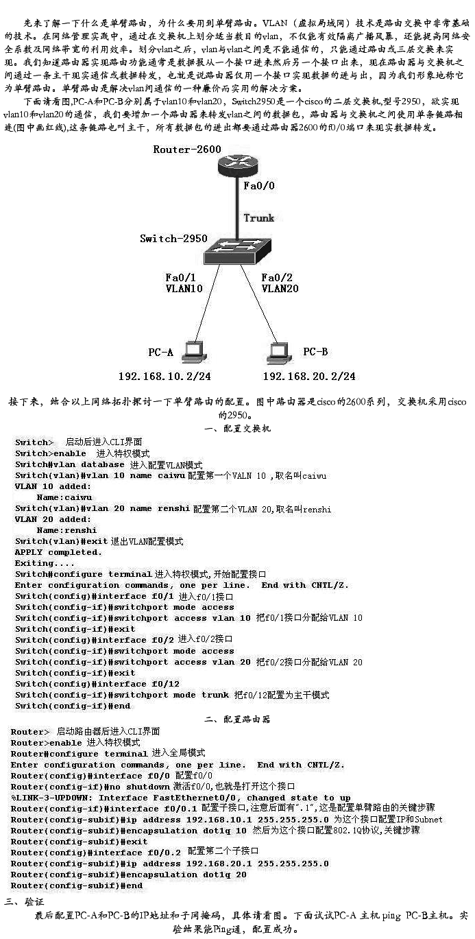
实验七 VLAN之间的路由及配置单臂路由
(一) VLAN之间的路由
1. 实验要求
l 将交换机划成2个VLAN;
l port 2,port 10,port 11 等3个端口加入VLAN 2
l 把路由器的FA0/0口加入VLAN 1 连接,FA0/1口加入VLAN 2连接。
l 仅使路由器的FA0/0与VLAN 1连接,配置单臂路由。
2. 实验拓扑
PCA : PCB:
IP 192.168.1.2 192.168.2.2
掩码 255.255.255.0 255.255.255.0
网关 192.168.1.1 192.168.2.1
3. 实验步骤
Switch:
#config t
#int fa0/2
#switchport mode access 将端口映射到VLAN2
#switchport access vlan 2
#exit
#int fa0/10
#switchport mode access
#switchport access vlan 2
#exit
#int fa0/11
#switchport mode access
#switchport access vlan 2
#exit
#show vlan
Router:
#conf t
#int fa0/0
#ip address 192.168.1.1 255.255.255.0
#no shut
#exit
#int fa0/1
#ip address 192.168.2.1 255.255.255.0
#no shut PCA ping PCB ?
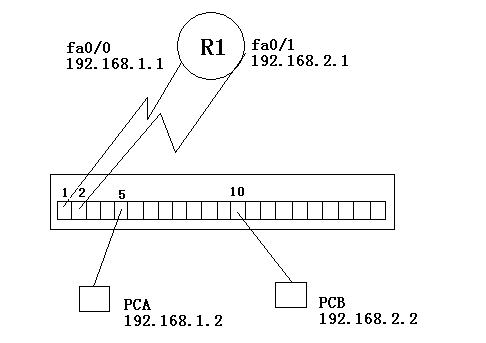
(二) 单臂路由
1. 实验要求
这时接入VLAN1的配置正确的计算机与接入VLAN2的配置正确的计算机可以正常通信,但多浪费路由器的一个接口和交换机的一个接口,方法不可行。
将连接路由器端口Fa0/1与交换机的线断开,形成单臂路由。
2.实验拓扑
3.实验步骤
Switch:
config t
int Fa0/1
switchport mode trunk 在端口上配置中继(2950)
 switchport trunk encapsulation dot1q 用dot1q进行封装
switchport mode trunk (3560)
router:
config t
int fa0/0
no ip address
exit
int fa0/1
no ip address
exit
int fa0/0.1
router(config-subif)# encapsulation dot1q 1
将子接口fa0/0.1设置为trunk,用dot1q封装,划分到VLAN1
router(config-subif)#ip address 192.168.1.1 255.255.255.0
(子接口封装后才能进行IP地址的配置)
router(config-subif)#no shut
router(config-subif)#exit
router(config)#int fa0/0.2
router(config-subif)#encapsulation dot1q 2
router(config-subif)#ip address 192.168.2.1 255.255.255.0
router(config-subif)#no shut
PCA ping PCB ?
配置前先输入:
Router#reload
------------------------------------(yes/no):no
Switch#reload
------------------------------------(yes/no):no