实验名称:数字时钟设计
实验仪器及软件:计算机,QUARTAS。
实验目的:
1全面了解如何应用该硬件描述语言进行高速集成电路设计;
2.通过对数字时钟软件设计环节与仿真环节熟悉Quartus II设计与仿真环境;
3. 通过对数字时钟的设计,掌握硬件系统设计方法(自底向上或自顶向下),熟悉VHDL语言三种设计风格,熟悉其芯片硬件实现的过程。
4 体会硬件设计语言在工程中的重要性。全面掌握设计方法和过程。
实验要求:设计一个数字时钟,并输出到数码管显示时,分,秒。
实验原理:
A 整体系统实行自顶下的原则,通过顶层实体分别串接各个设计部件,各个部件接口通过端口映射的方式进行串接,从而达到设计目的。
B 整个程序中涉及的部件有:(1)分频器,对输入时钟40Mhz进行40000000分频,得到1Hz信号,作为计数器的计数时钟;对输入时钟40Mhz进行400000分频,得到100Hz信号,作为数码显示管位扫描信号(2)计数器,用24进制计数器作为小时位的计数,用60进制计数器作为分位,秒位的计数。(3)位选程序,实现六个数码显示管动态扫描显示,(4)LED显示程序:用于显示信号在数码管。(5)顶层模块实体部分,指明了输入输出端口,各部分的联系和链接,以及通过端口映射连接各部分,实现整个程序功能。
C 关于动态显示,扫描频率设置为100HZ,这个频率大于要求的50HZ,利用人眼的视觉暂留效果,则看不到闪烁现象,可以实现动态显示功能。
D 在计数器的时钟选择上,选择的是1HZ频率,满足了每秒一次的要求。
设计思路及VHDL代码
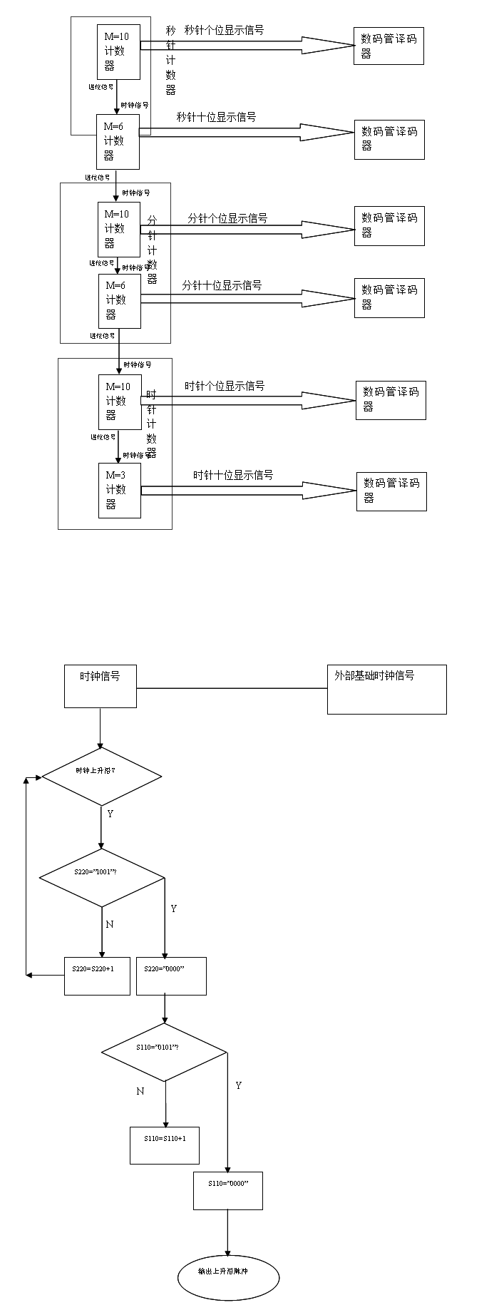
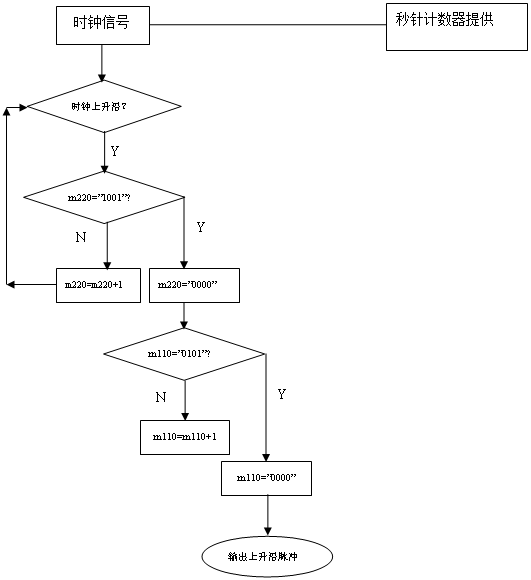
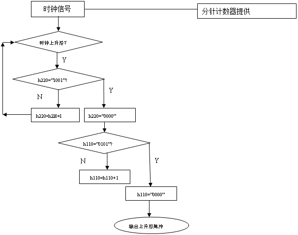
E两个模60的计数器来代表时钟的秒针,分针,再用一个模23的计数器来代替时针。外部基础时钟信号作为秒针计数器的时钟信号,秒针计数器的近进位信号作为分针计数器的时钟信号,分针计数器的进位信号有作为时针计数器的时钟信号,最后在统一输出。需要注意的是到23时59分59秒后下次跳动清零,从头开始。基础时钟信号选择1HZ最为简单。我们做了以40MHZ为基础时钟信号的时钟,主要要点在将40MHZ分频到1HZ。
下面通过原理结构图描述系统
一,顶层实体模块源代码
数字钟的顶层模块程序 clock.vhd
library ieee;
use ieee.std_logic_1164.all;
use ieee.std_logic_unsigned.all;
use ieee.std_logic_arith.all;
entity clock is
port(clk :in std_logic;
set :in std_logic;
qin_s_1 : in std_logic_vector(3 downto 0); --秒钟的低位调整输入端
qin_s_2 : in std_logic_vector(3 downto 0); --秒钟的高位调整输入端
qin_m_1 : in std_logic_vector(3 downto 0); --分钟的低位调整输入端
qin_m_2 : in std_logic_vector(3 downto 0); --分钟的高位调整输入端
qin_h_1 : in std_logic_vector(3 downto 0); --时钟的低位调整输入端
qin_h_2 : in std_logic_vector(3 downto 0); --时钟的高位调整输入端
qout : out std_logic_vector(6 downto 0); --7段码输出
sel : out std_logic_vector(5 downto 0) --位选输出端
);
end clock;
architecture behave of clock is
component cnt24 is
port(clk : in std_logic;
set : in std_logic;
din1 : in std_logic_vector(3 downto 0);
din2 : in std_logic_vector(3 downto 0);
qout1 : out std_logic_vector(3 downto 0);
qout2 : out std_logic_vector(3 downto 0));
end component cnt24;
component cnt60 is
port(clk : in std_logic;
set : in std_logic;
din1 : in std_logic_vector(3 downto 0);
din2 : in std_logic_vector(3 downto 0);
qout1 : out std_logic_vector(3 downto 0);
qout2 : out std_logic_vector(3 downto 0);
carry : out std_logic);
end component cnt60;
component fen1 is
port(clk:in std_logic;
qout:out std_logic);
end component fen1;
component fen100 is
port(clk:in std_logic;
qout:out std_logic);
end component fen100;
component weixuan is
port(clk : in std_logic;
qin1 : in std_logic_vector(3 downto 0);
qin2 : in std_logic_vector(3 downto 0);
qin3 : in std_logic_vector(3 downto 0);
qin4 : in std_logic_vector(3 downto 0);
qin5 : in std_logic_vector(3 downto 0);
qin6 : in std_logic_vector(3 downto 0);
qout : out std_logic_vector(3 downto 0);
sel : out std_logic_vector(5 downto 0));
end component weixuan;
component led_driv is
port(qin : in std_logic_vector(3 downto 0);
qout : out std_logic_vector(6 downto 0));
end component led_driv;
signal carry1: std_logic;
signal carry2: std_logic;
signal qout1 : std_logic;
signal qout100 : std_logic;
signal qout_s_1:std_logic_vector(3 downto 0);
signal qout_s_2:std_logic_vector(3 downto 0);
signal qout_m_1:std_logic_vector(3 downto 0);
signal qout_m_2:std_logic_vector(3 downto 0);
signal qout_h_1:std_logic_vector(3 downto 0);
signal qout_h_2:std_logic_vector(3 downto 0);
signal qoutI:std_logic_vector(3 downto 0);
begin
U0:fen1 port map(clk=>clk,qout=>qout1);
U1:fen100 port map(clk=>clk,qout=>qout100);
U2:cnt60 port map(clk=>qout1,set=>set,din1=>qin_s_1,din2=>qin_s_2,qout1=>qout_s_1,qout2=>qout_s_2,carry=>carry1);
U3:cnt60 port map(clk=>carry1,set=>set,din1=>qin_m_1,din2=>qin_m_2,qout1=>qout_m_1,qout2=>qout_m_2,carry=>carry2);
U4:cnt24 port map(clk=>carry2,set=>set,din1=>qin_h_1,din2=>qin_h_2,qout1=>qout_h_1,qout2=>qout_h_2);
U5:weixuan port map(clk=>qout100,qin1=>qout_s_1,qin2=>qout_s_2,qin3=>qout_m_1,qin4=>qout_m_2,qin5=>qout_h_1,qin6=>qout_h_2,qout=>qoutI,sel=>sel);
U6:led_driv port map(qin=>qoutI,qout=>qout);
end behave;
这部分实现的是顶层实体,它是程序的核心,通过端口映射把其他各部件程序端口连接为一个整体,指明系统的输入端口,输出端口,输入型号,输出信号。
二,分频部分
1,功 能:对输入时钟40Mhz进行40000000分频,得到1Hz信号
接 口:clk -时钟输入
qout-秒输出信号
library ieee;
use ieee.std_logic_1164.all;
entity fen1 is
port(clk:in std_logic;
qout:out std_logic);
end fen1;
architecture behave of fen1 is
constant counter_len:integer:=10#39999999#;
signal cnt:integer range 0 to counter_len;
begin
process(clk)
begin
if clk'event and clk='1' then
case cnt is
when 0 to counter_len/2=>qout<='0';
when others =>qout<='1';
end case;
if cnt=counter_len then
cnt<=0;
else
cnt<=cnt+1;
end if;
end if;
end process;
end behave;
这部分是用于实现分频得到1HZ频率,用于计数器的计数时钟,主要的思路:0—20MHZ为低电平,20—40MHZ划为高电平,然后时间分频得1HZ。
2功 能:对输入时钟40Mhz进行400000分频,得到100Hz信号,
作为数码显示管位扫描信号
接 口:clk -时钟输入
qout-100Hz输出信号
library ieee;
use ieee.std_logic_1164.all;
entity fen100 is
port(clk:in std_logic;
qout:out std_logic);
end fen100;
architecture behave of fen100 is
constant counter_len:integer:=10#399999#;
signal cnt:integer range 0 to counter_len;
begin
process(clk)
begin
if clk'event and clk='1' then
case cnt is
when 0 to counter_len/2=>qout<='0';
when others=>qout<='1';
end case;
if cnt=counter_len then
cnt<=0;
else
cnt<=cnt+1;
end if;
end if;
end process;
end behave;
这部分实现了由40MHZ分频得到100HZ频率,用于动态显示频率的产生。
三,功 能:实现六个数码显示管动态扫描显示
--接 口:clk -时钟输入
-- qin1-第一个数码显示管要显示内容输入
-- qin2-第二个数码显示管要显示内容输入
-- qin3-第三个数码显示管要显示内容输入
-- qin4-第四个数码显示管要显示内容输入
-- qin5-第五个数码显示管要显示内容输入
-- qin6-第六个数码显示管要显示内容输入
-- sel -位选信号输出
-------------------------------------------------
library ieee;
use ieee.std_logic_1164.all;
use ieee.std_logic_unsigned.all;
use ieee.std_logic_arith.all;
entity weixuan is
port(clk : in std_logic;
qin1 : in std_logic_vector(3 downto 0);
qin2 : in std_logic_vector(3 downto 0);
qin3 : in std_logic_vector(3 downto 0);
qin4 : in std_logic_vector(3 downto 0);
qin5 : in std_logic_vector(3 downto 0);
qin6 : in std_logic_vector(3 downto 0);
qout : out std_logic_vector(3 downto 0);
sel : out std_logic_vector(5 downto 0));
end weixuan;
architecture behave of weixuan is
begin
process(clk)
variable cnt:integer range 0 to 5;
begin
if clk'event and clk='1' then
case cnt is
when 0=>qout<=qin1;
sel<="111110";
when 1=>qout<=qin2;
sel<="111101";
when 2=>qout<=qin3;
sel<="111011";
when 3=>qout<=qin4;
sel<="110111";
when 4=>qout<=qin5;
sel<="101111";
when 5=>qout<=qin6;
sel<="011111";
when others=>qout<="0000";
sel<="111111";
end case;
if cnt=5 then
cnt:=0;
else
cnt:=cnt+1;
end if;
end if;
end process;
end behave;
这部分程序实现的是位选功能,用于动态显示,调整秒位,分位,时位。
四,计数器的设计
功 能:24进制计数器
--接 口:clk -时钟输入
-- set -时间使能端
-- din1 -个位数据预置输入
-- din2 -十位数据预置输入
-- qout1-个位BCD输出
-- qout2-十位BCD输出
library ieee;
use ieee.std_logic_1164.all;
use ieee.std_logic_unsigned.all;
use ieee.std_logic_arith.all;
entity cnt24 is
port(clk : in std_logic;
set : in std_logic;
din1 : in std_logic_vector(3 downto 0);
din2 : in std_logic_vector(3 downto 0);
qout1 : out std_logic_vector(3 downto 0);
qout2 : out std_logic_vector(3 downto 0));
end cnt24;
architecture behave of cnt24 is
signal tem1:std_logic_vector(3 downto 0);
signal tem2:std_logic_vector(3 downto 0);
begin
process(clk,set,din1,din2)
begin
if set='1' then
tem1<=din1;
tem2<=din2;
elsif clk'event and clk='1' then
if (tem2="0010" and tem1="0011") then
tem1<="0000";
tem2<="0000";
elsif(tem2/="0010" and tem1="1001") then
tem2<=tem2+1;
tem1<="0000";
else
tem2<=tem2;
tem1<=tem1+1;
end if;
end if;
end process;
qout1<=tem1;
qout2<=tem2;
end behave;
这部分设计了一个24进制计数器,用于小时位的计数,解决了时钟位显示的问题。
--功 能:24进制计数器
--接 口:clk -时钟输入
-- set -时间使能端
-- din1 -个位数据预置输入
-- din2 -十位数据预置输入
-- qout1-个位BCD输出
-- qout2-十位BCD输出
-------------------------------------------------
library ieee;
use ieee.std_logic_1164.all;
use ieee.std_logic_unsigned.all;
use ieee.std_logic_arith.all;
entity cnt24 is
port(clk : in std_logic;
set : in std_logic;
din1 : in std_logic_vector(3 downto 0);
din2 : in std_logic_vector(3 downto 0);
qout1 : out std_logic_vector(3 downto 0);
qout2 : out std_logic_vector(3 downto 0));
end cnt24;
architecture behave of cnt24 is
signal tem1:std_logic_vector(3 downto 0);
signal tem2:std_logic_vector(3 downto 0);
begin
process(clk,set,din1,din2)
begin
if set='1' then
tem1<=din1;
tem2<=din2;
elsif clk'event and clk='1' then
if (tem2="0010" and tem1="0011") then
tem1<="0000";
tem2<="0000";
elsif(tem2/="0010" and tem1="1001") then
tem2<=tem2+1;
tem1<="0000";
else
tem2<=tem2;
tem1<=tem1+1;
end if;
end if;
end process;
qout1<=tem1;
qout2<=tem2;
end behave;
这个部分设计了一个60进制计数器,用于分位,和秒位的设计,解决了分,秒计数的问题。
五,显示部分设计
--功 能:实现共阴数码显示管的编码显示
--接 口:qin -BCD码输入
-- qout-七段码输出
-------------------------------------------------
library ieee;
use ieee.std_logic_1164.all;
entity led_driv is
port(qin : in std_logic_vector(3 downto 0);
qout : out std_logic_vector(6 downto 0));
end led_driv;
architecture behave of led_driv is
begin
process(qin)
begin
case qin is
when "0000"=>qout<="0111111"; --显示0
when "0001"=>qout<="0000110"; --显示1
when "0010"=>qout<="1011011"; --显示2
when "0011"=>qout<="1001111"; --显示3
when "0100"=>qout<="1100110"; --显示4
when "0101"=>qout<="1101101"; --显示5
when "0110"=>qout<="1111101"; --显示6
when "0111"=>qout<="0000111"; --显示7
when "1000"=>qout<="1111111"; --显示8
when "1001"=>qout<="1101111"; --显示9
when others=>NULL;
end case;
end process;
end behave; --
这部分的设计用于数码管上的显示,动态扫描的频率用100HZ,这个频率是分频得到的。解决了数字显示的问题。
实验结果和分析
数字时钟显示仿真图
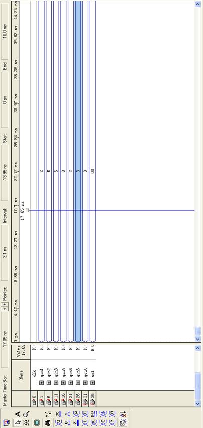
整体输入输出数字时钟显示仿真
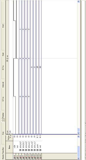
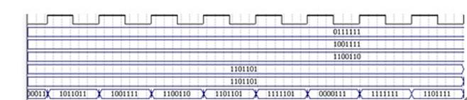
如上图所示,clk1为外部输入时钟信号为,qout依次为时钟各位对应数码管的信号.图二所示数码管上显示。
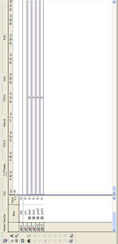
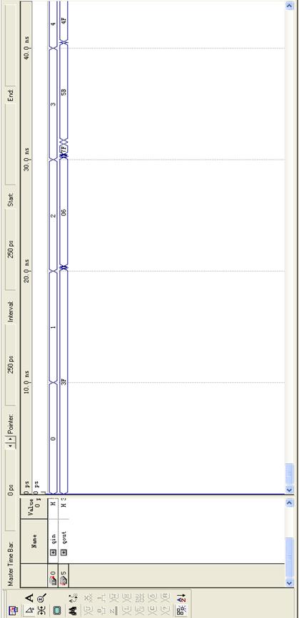
二十四进制计数器仿真图
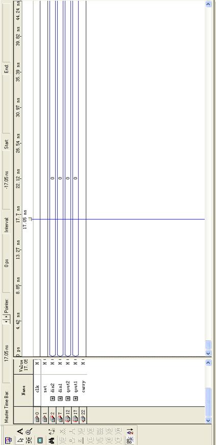
六十进制计数器仿真图
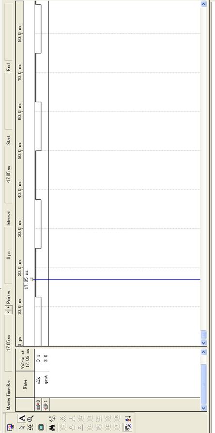
100HZ分频器仿真图
位选部分仿真图
LED显示仿真图
故障排除及问题分析
1,开始时,分频器没有设计,直接将现有频率加入,没有显示出结果,后反复思考,加入了分频器部分,重新将端口调整,成功显示出了结果。
2,在老师的指导下,有加入了报时功能,事先选择的是将到12:00:00直接送一个信号给输出端,事先报时,设计程序如下
library ieee;
use ieee.std_logic_1164.all;
use ieee.std_logic_unsigned.all;
use ieee.std_logic_arith.all;
entity baoshi is
port(
qin_s_1 : in std_logic_vector(3 downto 0); --秒钟的低位调整输入端
qin_s_2 : in std_logic_vector(3 downto 0); --秒钟的高位调整输入端
qin_m_1 : in std_logic_vector(3 downto 0); --分钟的低位调整输入端
qin_m_2 : in std_logic_vector(3 downto 0); --分钟的高位调整输入端
qin_h_1 : in std_logic_vector(3 downto 0); --时钟的低位调整输入端
qin_h_2 : in std_logic_vector(3 downto 0); --时钟的高位调整输入端
qout : out std_logic_vector(3 downto 0)
);
end baoshi;
architecture behave of baoshi is
signal tem1:std_logic_vector(3 downto 0);
signal tem2:std_logic_vector(3 downto 0);
signal tem3:std_logic_vector(3 downto 0);
signal tem4:std_logic_vector(3 downto 0);
signal tem5:std_logic_vector(3 downto 0);
signal tem6:std_logic_vector(3 downto 0);
begin
process(qin_s_1,qin_s_2,qin_m_1,qin_m_2,qin_h_1,qin_h_2)
begin
tem1<=qin_s_1;
tem2<=qin_s_2;
tem3<=qin_m_1;
tem4<=qin_m_2;
tem5<=qin_h_1;
tem6<=qin_h_2;
if (tem1="0000" and tem2="0000" and tem3="0000" and tem4="0000" and tem5="0010" and tem6="0001")then
qout<="0101";
end if;
end process;
end behave;
仿真图结果
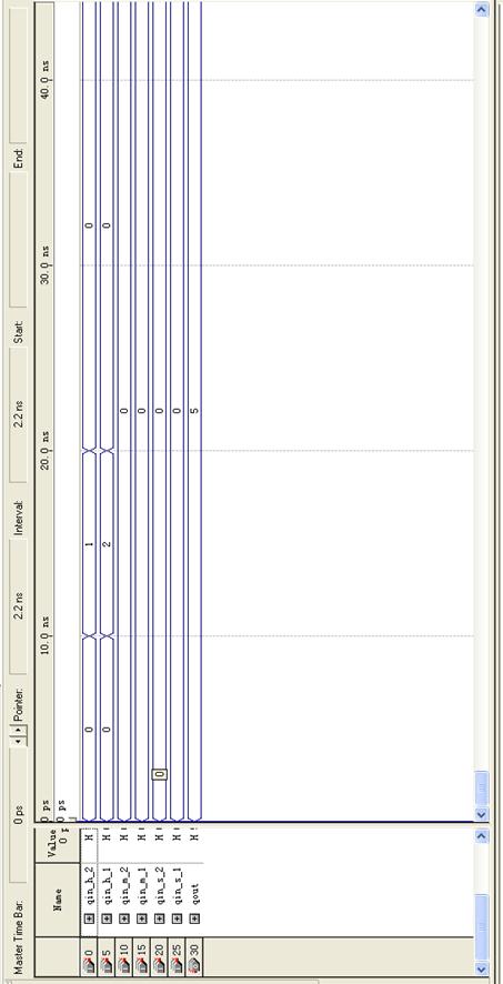
经过老师的指导,可以直接用进位信号产生报时系统输入信号,受益很多。
实验小结
1通过本次实验的设计,进行了逻辑分析,逻辑设计到源程序设计,然后进行调试,波形的仿真,一系列的设计工作后,成功的设计出了数字时钟显示程序。
2,进行实验,首先要解决系统结构,然后将系统结构的各个部件联系起来,设计各个部件并把各部件分别设计。分析存在的问题,理清设计的思路,将整个程序分工,再合并,达到要求的效果
3在设计过程中,收到了老师们的指导,同学的帮助,让我明白了VHDL设计可以是分模块化的,可以有分工合作。
4通过第三次实验,更加深入地了解和熟悉了VHDL语言。能比较灵活地使用VHDL语言。特别是这次实验中对于分频部分代码的编写。
5对于VHDL课程设计的理解越来越深刻,渐渐的便越加喜欢, VHDL课程设计是一门很好很有趣的课程。非常值得我们去深入学习。