电子电路设计数字部分实验报告

实验一 简单组合逻辑设计
实验内容
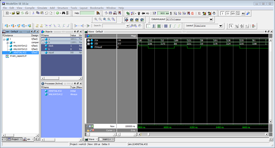
描述一个可综合的数据比较器,比较数据a 、b的大小,若相同,则给出结果1,否则给出结果0。
实验仿真结果
实验代码
主程序
module compare(equal,a,b);
input[7:0] a,b;
output equal;
assign equal=(a>b)?1:0;
endmodule
测试程序
module t;
reg[7:0] a,b;
reg clock,k;
wire equal;
initial
begin
a=0;
b=0;
clock=0;
k=0;
end
always #50 clock = ~clock;
always @ (posedge clock)
begin
a[0]={$random}%2;
a[1]={$random}%2;
a[2]={$random}%2;
a[3]={$random}%2;
a[4]={$random}%2;
a[5]={$random}%2;
a[6]={$random}%2;
a[7]={$random}%2;
b[0]={$random}%2;
b[1]={$random}%2;
b[2]={$random}%2;
b[3]={$random}%2;
b[4]={$random}%2;
b[5]={$random}%2;
b[6]={$random}%2;
b[7]={$random}%2;
end
initial
begin #100000 $stop;end
compare m(.equal(equal),.a(a),.b(b));
endmodule
实验二 简单分频时序逻辑电路的设计
实验内容
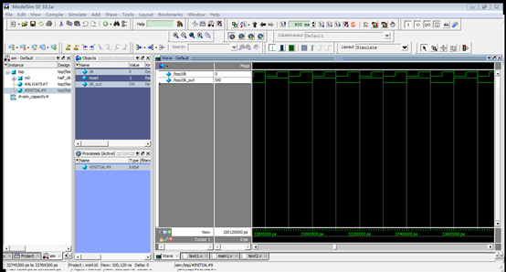
用always块和@(posedge clk)或@(negedge clk)的结构表述一个1/2分频器的可综合模型,观察时序仿真结果。
实验仿真结果
实验代码
主程序
module half_clk(reset,clk_in,clk_out);
input clk_in,reset;
output clk_out;
reg clk_out;
always@(negedge clk_in)
begin
if(!reset)
clk_out=0;
else
clk_out=~clk_out;
end
endmodule
测试程序
`timescale 1ns/100ps
`define clk_cycle 50
module top;
reg clk,reset;
wire clk_out;
always #`clk_cycle clk=~clk;
initial
begin
clk=0;
reset=1;
#10 reset=0;
#110 reset=1;
#100000 $stop;
end
half_clk m0(.reset(reset),.clk_in(clk),.clk_out(clk_out));
endmodule
实验三 利用条件语句实现计数分频时序电路
实验内容
利用10MHz的时钟,设计一个单周期形状的周期波形。
实验仿真结果

实验代码
主程序
module fdivision(RESET,F10M,out);
input F10M,RESET;
output out;
reg out;
reg[7:0] i;
always @(posedge F10M)
if(!RESET)
begin
out<=0;
i<=0;
end
else if(i==2||i==3)
begin
out=~out;
i<=i+1;
end
else if(i==5)
i<=1;
else
i<=i+1;
endmodule
测试程序
`timescale 1ns/100ps
module division_top;
reg F10M,RESET;
wire out;
always #50 F10M=~F10M;
initial
begin
RESET=1;
F10M=0;
#90 RESET=0;
#100 RESET=1;
#10000 $stop;
end
fdivision fdivision(.RESET(RESET),.F10M(F10M),.out(out));
endmodule
实验四 阻塞赋值与非阻塞赋值的区别
实验内容
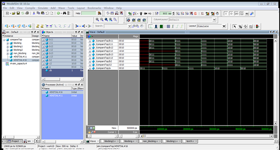
比较四种不同的写法,观察阻塞与非阻塞赋值的区别。
Blocking:
always @(posedge clk)
begin
b=a;
c=b;
end
Blocking1:
always @(posedge clk)
begin
c=b;
b=a;
end
Blocking2:
always @(posedge clk) b=a;
always @(posedge clk) c=b;
non_Blocking:
always@(posedge clk)
begin
b<=a;
c<=b;
End
实验仿真结果
实验代码
主程序
module blocking(clk,a,b,c);
output[3:0] b,c;
input[3:0] a;
input clk;
reg[3:0] b,c;
always @(posedge clk)
begin
b=a;
c=b;
end
endmodule
测试部分
`timescale 1 ns/100 ps
`include "./blocking.v"
`include "./blocking1.v"
`include "./blocking2.v"
`include "./non_blocking.v"
module compareTop;
wire[3:0]b11,c11,b12,c12,b13,c13,b2,c2;
reg[3:0]a;
reg clk;
initial
begin
clk=0;
forever#50 clk=~clk;
end
initial
begin
a=4'h3;
$display("%d",a);
#100 a=4'h7;
$display("%d",a);
#100 a=4'hf;
$display("%d",a);
#100 a=4'ha;
$display("%d",a);
#100 a=4'h2;
$display("%d",a);
#100 $stop;
end
blocking blocking(clk,a,b11,c11);
blocking1 blocking1(clk,a,b12,c12);
blocking2 blocking2(clk,a,b13,c13);
non_blocking non_blocking(clk,a,b2,c2);
endmodule
实验五 用always块实现较复杂的组合逻辑
实验目的
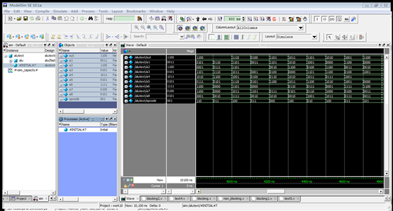
运用always块设计一个8路数据选择器。要求:每路输入数据与输出数据均为4位2进制数,当选择开关(至少3位)或输入数据发生变化时,输出数据也相应地变化。
实验仿真结果
实验代码
主程序
module alu(out,opcode,a1,a2,a3,a4,a5,a6,a7,a8);
output[3:0] out;
reg[3:0] out;
input[3:0] a0,a1,a2,a3,a4,a5,a6,a7;
input[2:0] opcode;
always@(opcode or a1 or a2 or a3 or a4 or a5 or a6 or a7 or a0)
begin
case(opcode)
3'd0: out=a0;
3'd1: out=a1;
3'd2: out=a2;
3'd3: out=a3;
3'd4: out=a4;
3'd5: out=a5;
3'd6: out=a6;
3'd7: out=a7;
default:out=4'b0000;
endcase
end
endmodule
测试程序
`timescale 1ns/1ns
`include "./main5.v"
module alutext;
wire[3:0] out;
reg[3:0] a1,a2,a3,a4,a5,a6,a7,a8;
reg[2:0] opcode;
initial
begin
a1={$random}%16;
a2={$random}%16;
a3={$random}%16;
a4={$random}%16;
a5={$random}%16;
a6={$random}%16;
a7={$random}%16;
a8={$random}%16;
repeat(100)
begin
#100 opcode={$random}%8;
a1={$random}%16;
a2={$random}%16;
a3={$random}%16;
a4={$random}%16;
a5={$random}%16;
a6={$random}%16;
a7={$random}%16;
a8={$random}%16;
end
#100 $stop;
end
alu alu(out,opcode,a1,a2,a3,a4,a5,a6,a7,a8);
endmodule
实验六 在 Verilog HDL中使用函数
实验目的
设计一个带控制端的逻辑运算电路,分别完成正整数的平方、立方和最大数为5的阶乘运算。
实验仿真结果
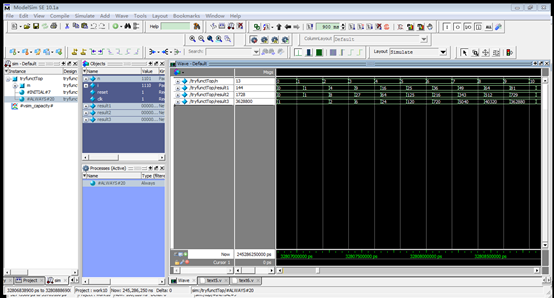
实验代码
主程序
module tryfunct(clk,n,result1,result2,result3,reset);
output[31:0]result1,result2,result3;
input[3:0]n;
input reset,clk;
reg[31:0]result1,result2,result3;
always@(posedge clk)
begin
if(!reset)
begin
result1<=0;
result2<=0;
result3<=0;
end
else
begin
result1<=fun1(n);
result2<=fun2(n);
result3<=fun3(n);
end
end
function[31:0]fun1;
input[3:0]operand;
fun1=operand*operand;
endfunction
function[31:0]fun2;
input[3:0]operand;
begin
fun2=operand*operand;
fun2=operand*fun2;
end
endfunction
function[31:0]fun3;
input[3:0]operand;
reg[3:0]index;
begin
fun3=1;
if(operand<11)
for(index=2;index<=operand;index=index+1)
fun3=index*fun3;
else
for(index=2;index<=10;index=index+1)
fun3=index*fun3;
end
endfunction
endmodule
测试程序
`include"./main6.v"
`timescale 1ns/100ps
module tryfunctTop;
reg[3:0] n,i;
reg reset,clk;
wire[31:0]result1,result2,result3;
initial
begin
clk=0;
n=0;
reset=1;
#100 reset=0;
#100 reset=1;
for(i=0;i<=15;i=i+1)
begin
#200 n=i;
end
#100 $stop;
end
always#50 clk=~clk;
tryfunct m(.clk(clk),.n(n),.result1(result1),.result2(result2),.result3(result3),.reset(reset));
endmodule
实验七 在Verilog HDL中使用任务(task)
实验目的
用两种不同方法设计一个功能相同的模块,该模块能完成四个8位2进制输入数据的冒泡排序。第一种,模仿原题例子中用纯组合逻辑实现;第二种,假设8位数据是按照时钟节拍串行输入的,要求用时钟触发任务的执行法,每个时钟周期完成一次数据交换操作。
实验仿真结果
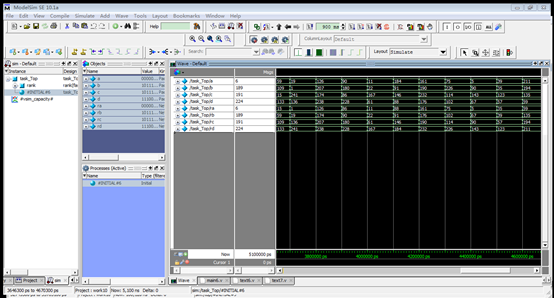
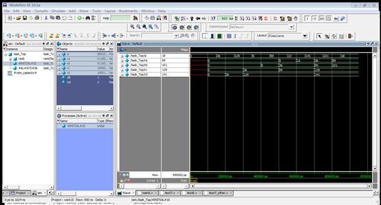
实验代码
主程序1
module rank(ra,rb,rc,rd,a,b,c,d);
output[7:0]ra,rb,rc,rd;
input[7:0]a,b,c,d;
reg[7:0]ra,rb,rc,rd,va,vb,vc,vd,tmp;
reg i;
always@(a or b or c or d)
begin
{va,vb,vc,vd}={a,b,c,d};
repeat(7)
begin
exchange(va,vb);
exchange(vb,vc);
exchange(vc,vd);
end
{ra,rb,rc,rd}={va,vb,vc,vd};
end
task exchange;
inout[7:0] x,y;
reg[7:0] tmp;
if(x>y)
begin
tmp=x;
x=y;
y=tmp;
end
endtask
endmodule
测试部分1
`timescale 1ns/100ps
`include "main7.v"
module task_Top;
reg[7:0]a,b,c,d;
wire[7:0]ra,rb,rc,rd;
initial
begin
a=0;b=0;c=0;d=0;
repeat(50)
begin
#100 a={$random}%255;
b={$random}%255;
c={$random}%255;
d={$random}%255;
end
#100 $stop;
end
rank rank(.ra(ra),.rb(rb),.rc(rc),.rd(rd),.a(a),.b(b),.c(c),.d(d));
endmodule
主程序2
module rank(a,rst,clk,ra,rb,rc,rd);
output[7:0]ra,rb,rc,rd;
input[7:0]a;
input clk,rst;
reg[7:0]ra,rb,rc,rd;
reg[7:0]va,vb,vc,vd;
reg[3:0]i;
always@(posedge clk or negedge clk)
begin
if(!rst)
begin
va=0;
vb=0;
vc=0;
vd=0;
i=0;
end
else
begin
if(i<8)
begin
i=i+1;
va=a;
exchange(va,vb);
exchange(vb,vc);
exchange(vc,vd);
exchange(va,vb);
exchange(vb,vc);
exchange(va,vb);
{ra,rb,rc,rd}={va,vb,vc,vd};
end
end
end
task exchange;
inout[7:0] x,y;
reg[7:0] tmp;
if(x>y)
begin
tmp=x;
x=y;
y=tmp;
end
endtask
endmodule
测试部分2
`timescale 1ns/100ps
`include "main7_other.v"
module task_Top;
reg[7:0]a;
wire[7:0]ra,rb,rc,rd;
reg clk,rst;
initial
begin
a=0;
rst=0;
clk=0;
#50 rst=1;
#100 a={8{$random}};
#100 a={8{$random}};
#100 a={8{$random}};
#100 a={8{$random}};
#100 a={8{$random}};
#100 a={8{$random}};
#100 a={8{$random}};
#100 a={8{$random}};
#100 $stop;
end
always #100 clk=~clk;
rank rank(.a(a),.rst(rst),.clk(clk),.ra(ra),.rb(rb),.rc(rc),.rd(rd));
endmodule
实验八 利用有限状态机进行时序逻辑的设计
实验目的
设计一个串行数据检测器。要求连续四个或四个以上为1 时输出1,其他输入情况下为0.
实验仿真结果
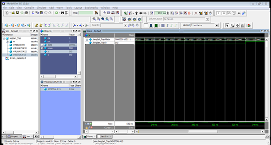
实验代码
主程序
module seqdet(x,z,clk,rst,state);
input x,clk,rst;
output z;
output[2:0] state;
reg[2:0] state;
wire z;
parameter IDLE='d0,A='d1,B='d2,C='d3,D='d4;
assign z=(state==D&&x==1)?1:0;
always@(posedge clk)
if(!rst)
begin
state<=IDLE;
end
else
casex(state)
IDLE:
if(x==1)
begin
state<=A;
end
A:
if(x==1)
begin
state<=B;
end
else
begin
state<=IDLE;
end
B:
if(x==1)
begin
state<=C;
end
else
begin
state<=IDLE;
end
C:
if(x==1)
begin
state<=D;
end
else
begin
state<=IDLE;
end
D:
if(x==1)
begin
state<=D;
end
else
begin
state<=IDLE;
end
default:state=IDLE;
endcase
endmodule
测试代码
`include "main8.v"
module seqdet_Top;
reg clk,rst;
reg[23:0] data;
wire[2:0] state;
wire z,x;
assign x=data[23];
always #10 clk=~clk;
always@(posedge clk)
data={data[22:0],data[23]};
initial
begin
clk=0;
rst=1;
#2 rst=0;
#30 rst=1;
data='b1001_1111_0111_1110;
#500 $stop;
end
seqdet m(x,z,clk,rst,state);
endmodule
实验九 楼梯灯
实验目的
? 楼下到楼上依次有3个感应灯:灯1、灯2、灯3。当行人上下楼梯时,各个灯感应到后自动点亮,若在8s内感应信号消失,则点亮8s,若感应信号存在时间超过8s,则感应信号消失4s后灯自动关闭。
? 任务1:做出如上逻辑电路设计并仿真;
? 任务2:考虑去抖情况,对于感应信号到达存在毛刺(小于0.5s),设计合适逻辑并剔出。
任务3:若为节约能源,下一个灯点亮的同时将自动关闭上一个灯,做出如上逻辑设计并仿真(仅考虑一个人的情况)
实验仿真结果

实验代码
主程序
module light_All(clk10,rst,switch,light);
input clk10,rst;
input[2:0]switch;
output[2:0]light;
reg[2:0]state1,state2,state3;
reg[7:0]count1,count2,count3;
reg[2:0]count_1,count_2,count_3;
reg[2:0]light;
parameter
state1_start=3'b000,state2_start=3'b000,state3_start=3'b000,
state1_work=3'b001,state2_work=3'b001,state3_work=3'b001,
state1_up=3'b010,state2_up=3'b010,state3_up=3'b010,
state1_down=3'b011,state2_down=3'b011,state3_down=3'b011,
state1_other=3'b100,state2_other=3'b100,state3_other=3'b100;
always@(posedge clk10)
if(!rst)
begin
state1<=state1_start;
count1<=8'b0;
count_1<=3'b0;
end
else
if(switch[0]=='b1&&count_1<4)
count_1<=count_1+1;
else
case(state1)
state1_start:
if(switch[0]=='b1)
begin
state1<=state1_up;
count1<=78;
end
else
begin
state1<=state1_start;
light[0]<='b0;
end
state1_work:
if(count1>0)
begin
count1<=count1-1;
if(switch[0]=='b0&&(state2==3'b010||state3==3'b010))
begin
light[0]<='b0;
state1<=state1_down;
end
end
else
if(switch[0]=='b0)
begin
state1<=state1_down;
end
else
begin
state1<=state1_other;
count1<=39;
end
state1_other:
if(switch[0]=='b1)
state1<=state1_other;
else
if(count1>0)
begin
count1<=count1-1;
if(switch[0]=='b0&&(state2==3'b010||state3==3'b010))
begin
light[0]<='b0;
state1<=state1_down;
end
end
else
state1<=state1_down;
state1_down:
begin
light[0]<='b0;
count_1<=3'b0;
state1<=state1_start;
end
state1_up:
begin
light[0]<='b1;
state1<=state1_work;
end
default:
state1<=state1_start;
endcase
always@(posedge clk10)
if(!rst)
begin
state2<=state2_start;
count2<=8'b0;
count_2<=3'b0;
end
else
if(switch[1]=='b1&&count_2<4)
count_2<=count_2+1;
else
case(state2)
state2_start:
if(switch[1]=='b1)
begin
state2<=state2_up;
count2<=78;
end
else
begin
state2<=state2_start;
light[1]<='b0;
end
state2_work:
if(count2>0)
begin
count2<=count2-1;
if(switch[1]=='b0&&(state1==3'b010||state3==3'b010))
begin
light[1]<='b0;
state2<=state2_down;
end
end
else
if(switch[1]=='b0)
begin
state2<=state2_down;
end
else
begin
state2<=state2_other;
count2<=39;
end
state2_other:
if(switch[1]=='b1)
state2<=state2_other;
else
if(count2>0)
begin
count2<=count2-1;
if(switch[1]=='b0&&(state1==3'b010||state3==3'b010))
begin
light[1]<='b0;
state2<=state2_down;
end
end
else
state2<=state2_down;
state2_down:
begin
light[1]<='b0;
count_2<=3'b0;
state2<=state2_start;
end
state2_up:
begin
light[1]<='b1;
state2<=state2_work;
end
default:
state2<=state2_start;
endcase
always@(posedge clk10)
if(!rst)
begin
state3<=state3_start;
count3<=8'b0;
count_3<=3'b0;
end
else
if(switch[2]=='b1&&count_3<4)
count_3<=count_3+1;
else
case(state3)
state3_start:
if(switch[2]=='b1)
begin
state3<=state3_up;
count3<=78;
end
else
begin
state3<=state3_start;
light[2]<='b0;
end
state3_work:
if(count3>0)
begin
count3<=count3-1;
if(switch[2]=='b0&&(state1==3'b010||state2==3'b010))
begin
light[2]<='b0;
state3<=state3_down;
end
end
else
if(switch[2]=='b0)
begin
state3<=state3_down;
end
else
begin
state3<=state3_other;
count3<=39;
end
state3_other:
if(switch[2]=='b1)
state3<=state3_other;
else
if(count3>0)
begin
count3<=count3-1;
if(switch[2]=='b0&&(state1==3'b010||state2==3'b010))
begin
light[2]<='b0;
state3<=state3_down;
end
end
else
state3<=state3_down;
state3_down:
begin
light[2]<='b0;
count_3<=3'b0;
state3<=state3_start;
end
state3_up:
begin
light[2]<='b1;
state3<=state3_work;
end
default:
state3<=state3_start;
endcase
endmodule
测试程序
`timescale 100ns/10ns
module test_light_All;
reg clk10,rst;
reg[2:0] up,down;
wire[2:0] swh;
wire[2:0] light;
parameter HALF_PERIOD = 5;
always #HALF_PERIOD clk10=~clk10;
initial
begin
clk10 = 0;
rst = 1;
up = 3'b000;down = 3'b000;
#1 rst = 0;
#10 rst = 1;
#100 up = 3'b001; down = 3'b000;
#500 up = 3'b010; down = 3'b100;
#600 up = 3'b011; down = 3'b010;
#30 up = 3'b010;
#80 up = 3'b011;
#900 up = 3'b010; down = 3'b001;
#500 up = 3'b101; down = 3'b001;
#600 up = 3'b000; down = 3'b101;
#80 down = 3'b111;
#30 down = 3'b101;
#100 up = 3'b011; down = 3'b010;
#500 up = 3'b100; down = 3'b101;
#500 up = 3'b101; down = 3'b000;
#600 up = 3'b010; down = 3'b110;
#100 up = 3'b111; down = 3'b001;
#200 up = 3'b000; down = 3'b000;
#1000 $stop;
end
assign swh = up | down;
light_All m5(clk10,rst,swh,light);
endmodule
总结
通过Verilog实验,可以让我们理解示范实验中的每一条语句,然后进行功能仿真可以加深我们对Verilog的理解,让我们对老师课堂上所讲的知识点有一个更加深入的了解,解决了很多我们在课堂学习中所不能解决的问题,比如阻塞赋值和非阻塞赋值的实验,就可以让我们更加清楚明白的了解阻塞赋值和非阻塞赋值的区别,避免了课堂讲解的难于理解,同时也加深了我们对这个知识点的记忆。通过做这些实验,可以让我们掌握基本组合逻辑电路的实现方法和生成方法,掌握测试模块的编写方法,掌握各种不同的语句在时序模块设计中的使用,了解Verilog语言中不同实现方法的区别,比如阻塞赋值和非阻塞赋值的区别,比如assign和always两种组合电路实现方法的区别,让我们可以学习测试模块的编写、综合和不同层次的仿真,可以通过综合和布局布线了解不同层次仿真的物理意义,让我们更加完整的了解Verilog,让我们更加深刻的了解我们所学到的知识,并学以所用,能够设计比较简单的程序以实现预期的功能。