
南 京 理 工 大 学 紫 金 学 院
电子工程与光电技术系
毕业设计(论文)开题报告
学 生 姓 名:
专 业:
设计(论文)题目:
指 导 教 师:
顾辰铭 学 号: 通信工程 110404221 基于WiFi的温度采集系统 武晓光
2015 年 1 月 1 日
开题报告填写要求
1.开题报告(含“文献综述”)作为毕业设计(论文)答辩委员会对学生答辩资格审查的依据材料之一。此报告应在指导教师指导下,由学生在毕业设计(论文)工作前期内完成,经指导教师签署意见及所在专业审查后生效;
2.开题报告内容必须用黑墨水笔工整书写或按教务处统一设计的电子文档标准格式(可从教务处网页上下载)打印,禁止打印在其它纸上后剪贴,完成后应及时交给指导教师签署意见;
3.“文献综述”应按论文的格式成文,并直接书写(或打印)在本开题报告第一栏目内,学生写文献综述的参考文献应不少于15篇(不包括辞典、手册);
4.有关年月日等日期的填写,应当按照国标GB/T 7408—2005《数据元和交换格式、信息交换、日期和时间表示法》规定的要求,一律用阿拉伯数字书写。如“20xx年3月15日”或“2007-03-15”。
毕 业 设 计(论 文)开 题 报 告

毕 业 设 计(论 文)开 题 报 告
毕 业 设 计(论 文)开 题 报 告

第二篇:开题报告_1(含文献综述)


毕业设计(论文)开题报告
(含文献综述、外文翻译)

题 目 任意素描边界线得到的可展曲面
姓 名
学 号
专业班级
指导教师
分 院
开题时间
文献综述内容
(包括国内外现状、研究方向、进展情况、存在问题、参考依据等)
基于手绘草图的交互式三维系统的研究
1.引言
随着计算机硬件和软件的发展,人和计算机之间的关系也发生了深刻变化。人机交互向着更透明,更灵活,更高效,更强大的方向进步,计算机在人们学习生活中的位置越来越重要,提供服务的方式也越来越友好和自然。用户逐渐成为交互式中的主体,人机交互模式朝着“用户自由”的方向发展。
在灵感充斥并易逝的工业设计领域中,对高效交互工具和设计模式以及交互技术的要求更加明显。工业产品的功能已不再是消费者决定购买的最主要因素,产品外观造型,宜人性等因素越来越受到重视,在竞争中占据突出地位。创新是工业设计的灵魂,以知识为基础的产品创新竞争是21世纪初全球制造业竞争的核心,一个新产品在功能,原理布局,形状,色彩,工艺等任一方面的创新,都会直接影响产品的整体特性。形状是产品的主要表现形式,是用户的第一刺激物,设计中的大部分活动都是围绕着形状进行,因此对形状的设计是一个很重要的方面。
笔式用户界面的发展,提供了一种更自然的交互方式,使新的交互工具,设计模式以及交互技术的出现成为必然,设计过程更加灵活自由。手势是笔式交互中的主要适用特征,用户可通过自由勾画方式直观自然地表达设计概念,促进了设计者直觉,灵感,想象力与创造力的充分发挥。
2.国内外现状以及发展趋势
在计算机图形学和建模领域里,对凸起的可展曲面提出几种不同的情境包括重建点[CLL*99 ,pet04]和网格分割成近显影图,参数化和模式设计[jks05 ,ygzs05,stl06]。以下回顾的只涵盖建模可展曲面通过显影逼近或直接的方法。
显影逼近:鉴于现有不可展曲面,有大量的方法,目的是逼近它的一个或多个面,包括[MS04,wt04,lpw*06,djw*06]。 Mitani and Suzuki [MS04] 逼近任意网格的三角地带; 展开后者构建近似初始几何二维样纸工艺品玩具。Wang和Tang[wt04]增加的一个网状表面最大限度地减少其高斯曲率。Frey用于一种相似的方法[Fre04]介绍单一端点可展的三角剖分。Decaudin等人的[DJW06]用途重叠的网格,估算每个网格当地最佳的接近的可展曲面和扭屈这表面的网格。一个相关的问题是由刘[lpw*06]等人提出一个解决平坦化,或发展,适用于特殊情况下的平面四方条状的算法。与细分结合它可以被用于塑造任何可展曲面。
在连续化格局中,这些表面往往代表用裁定的Bézier或B样条曲线和是被强迫使用非线性约束[aum04,cs02] 。要求用户为曲面明显地指定直母线方向。Wang
和Tang[ wt05]用一个离散建模切点面。对他们的方法的输入是二条折线准线,并且产品是每个内部边接近连接二条准线的判决的可展的三角小条。Pottman和Walner[PW01]使用一种对偶空间方法定义塑造的可展一个基于平面的控制接口。控制这种接口需要大量的几何知识。
自1963年Ivan Sutherland【1】发明画板以来,很多计算机图形系统由用户的绘制隐喻(metaphor)来继续三维形体建模,通常多数都要求用户绘制线框模型的多边形biao面。但是,这种非直观的CAD方式使得解决方案脱离了绘画创作一般的实践经验。值得一提的是Eggli【2】尝试更直观的建模以减轻用户三维操作的负担,但其对用户绘制操作的解释有歧异。
和以上方法不同,Teddy【3】是基于手势(gesture-based)的交互,在三维建模方面更为强大直观,但是,他的简单性是由限制表面形状(方盒状,圆形)或模型拓扑结构代价换来的。
近年来,图形学领域已经开发了大量的3D建模和可视化工具,但是这些工具的界面往往过于复杂,制约了设计人员的创造性工作,也进一步限制了这些工具为普遍用户所使用。事实上,理想的3D建模工具应谊提供给用户以尽可能自然、简单的操作,例如基于电子笔的草图输入,而且随着移动设备的发展。也使之成为图形学中更有前景的研究方向。提出了一个更加智能化的多模块建模体系.突出了交互技术、智能理解和高质量的可视化输出技术的结合;而且针对手绘输入的不明确性,着重分析了图形数据的基于特性的语义描述,提出了智能的逻辑推理模型,并进一步描述了下一代融合自然输入、逻辑推理与虚拟显示于一体的智能图形建模系统的实现。预测了人工智能技术与CAD技术的结合将是未来图形学领域发展的主要方向之一。
在商业系统中,Arisan是从交互纹理界面获得的启示,带一般绘制隐喻的Maya软件工具集。它也采用基于手势的交互设计方式,用户可以采用相应的画刷或造型工具直观的推,拉编辑曲面。虽然同样采用了基于手势的交互方式,但Zbrush极大地扩展了Maya Artisan塑造一个粗糙的封闭原型形状,再由多分辨率的细分曲面功能继续求精。此外,在计算机辅助设计领域,草图建模的商业软件也有了一定程度的应用,如基于SKETCH的草图建筑设计系统SketchUp。
3.研究方向
基于用户自由的交互模式,采用纸笔交互隐喻下的手势操作模式并以草图为信息载体来进行概念设计,探讨了内部新式交互技术,为概念设计阶段提供一种自然和谐的用户界面。提供能动性的交互工具和技术是提高设计效率的关键所在。
分析草图和手势的研究现状及其发展状况,遵循用户的交互模式,基于无处不在的计算的交互理念,引入了新的交互技术,提出基于手势和草图的能动性交互设计工具,支持设计过程,研究基于手势和草图的概念设计思维模型和过程模型。
基于笔式交互设计,以用户为中心,支持概念设计基于手绘草图的特征手势建模方式,使得用户将传统设计的优点和计算机设计的优点很好地结合起来。将手势自然地融合到特征设计中,代替原来按钮方式,简化繁杂的交互过程,使得交互式更加和谐。
以多边形网格模型为代表的三维数字信号,包含几何和拓扑,是继声音,图像和视频之后被人们公认为的第四代多媒体数据类型。同时,随着三维多边形网格模型在工业界的广泛适用,基于网格的造型和处理技术的应用领域也越来越广。譬如,在以三维动画为主的影视制作中,为了表示真实世界中复杂的几何形状,看上去质地绚丽的物体和场景,就必须将模型分解成足够多的三角形。另外,在制造行业,我们通常还需要对输入的三维模型进行编辑和处理。其它应用领域,包括计算机游戏行业,CAD和电子商务,也涉及对三维模型的造型和处理。
可展曲面射影几何:可展曲面的一个重要特征是他们的标准图是一维的[PW01]。 在一般情况下(图4) ,标准图是曲线网格。如果标准图是唯一的曲线,则表面的准线是唯一连续的曲线。Pottman和Walner [PW01]提及这些表面作为可展的直纹面表面或绕切的直纹面。为了避免混淆直纹面表面,我们将参考这些表面作为点显影表面上,在对比一般曲面,其标准图是网格曲线。一般可可展曲面因而被做转折平面区域一起加入的绕切的可展曲面联合[dC76],其中后者对应于在标准图的分支点。
4.存在的问题
传统的三维动画模型通常利用三维扫描设备直接获得或通过3DS MAX,MAYA等三维处理软件建模完成。但专业三维扫描硬件往往需要较高的成本。而三维建模软件虽然采用交互界面来简化从二维输入确定三维操作的步骤,用户能在可视化窗口从不同视点观察编辑以准确创建各类模型,但运用此类三维软件建模却不可避免地需要一系列繁琐,复杂且不直观的操作。这些繁复的操作另初学者望而却步,而且也不利于艺术家进行快速原型创作与交流。
人们常常以勾勒,涂鸦的方式保存思维的轨迹或和与他人交流看法。相比文字表达,绘图往往能更加快捷和简明的描述三维外形或空间关系。虽然绘画工具的使用方式都比较简单,但这些简单的方式在人类长时间的绘画时间中灵活组合最终形成丰富的绘画经验。可是绘画的实践经验很少被用到除二维绘制或基于图像绘制以外的计算机图形学领域。同时由于快速建模与原型工具的缺失,实际中艺术家只有当他们需求确定和构思成熟的时候才会求助于计算机辅助系统,传统的建模工具不适合用于灵感形成阶段。
5.参考文献
[1] G. Borgefors. Distance transformations in arbitrary dimen-sions. In Proc. of Computer Vision, Graphics, and Image Processing, 27(3):321–345, 1984.
[2] D. Bourguignon, M.-P. Cani, and G. Drettakis. Drawing for illustration and annotation in 3d. Computer Graphics Forum, 20(3):114–122, 2001.
[3] J. M. Cohen, L. Markosian, R. C. Zeleznik, J. F. Hughes, and R. Barzel. An interface for sketching 3d curves. In ACM Symposium on Interactive 3D Graphics, pages 17–22, April 1999.
[4] T. Igarashi, S. Matsuoka, and H. Tanaka. Teddy: A sketch- ing interface for 3d freeform design. In Proceedings of SIGGRAPH 1999, pages 409–416, July 1999.
[5] S. F. Johnson. Lumo: illumination for cel animation. In Proceedings of the Symposium on Non-photorealistic animation and rendering, pages 45–52, 2002.
[6] Provot X. Animation realiste de vetements, Ph.D. thesis, Universite ´ Rene ´ Descartes; 1997.
[7] Volino P, Magnenat-Thalmann N. Virtual clothing: theory and practise. Heidelberg, Germany: Springer; 2000.
[8] Hauth M, Etzmu O, Eberhardt B, Sarlette R, Sattler M, Daubert K, Kautz J. Cloth animation and rendering, In: Tutorials Euro-graphics’02; 2002.
[9] House DH, Breen DE. Cloth modelling and animation. Natik, MA: AK Peters Ltd; 2000.
[10]SEDYKHV: Structure of the convex hull of a space curve. J. of Soviet Mathematics 33, 1 (1986), 1140–1153.
[11]SINGH K, FIUME E: Wires: A geometric deformation technique. Computer Graphics 32, Annual Conference Series (1998), 405–414.
[12]SHELDEND. R.:Digital surface representation and the constructibility of Gehry’s architecture. MIT,2002.
[13] SHATZI., TALA., LEIFMANG: Paper craft models from meshes. Vis. Comput. 22, 9 (2006), 825–834.
[14]WANG C. C. L., TANG K.: Achieving developability of a polygonal surface by minimum deformation: a study of global and local optimization approaches. The Visual Computer 20, 8-9 (2004), 521–539.
[15]WANG C. C. L., TANGK.: Optimal boundary triangulations of an interpolating ruled surface. Journal of Computing and Information Science in Engineering, ASME Transactions 5, 4 (2005), 291–301.
[16] YAMAUCHIH, GUMHOLDS, ZAYER, SEIDELH.-P.: Mesh segmentation driven by gaussian curvature. The Visual Computer 21, 8-10 (September 2005), 649–658.
[17]JULIUSD, KRAEVOYV., SHEFFERA:D-charts: Quasi-developable mesh segmentation. Computer Graphics Forum (Proc. Eurographics) 24, 3 (2005), 581–590.
[18] KARPENKO O. A, HUGHES J: Smooths-ketch:3D free-form shapes from complex sketches. ACM Transactions on Graphics 25, 3 (2006), 589–598.
[19] LAY S. R:Convex Sets and their Applications.Wiley, NY, 1972.
[20]LIU Y, POTTMANNH., WALLNER J., YANGY.-L., WANG ACM Transactions on Graphics 25, 3 (2006), 681–689.
[21] DO CARMOM.: Differential Geometry of Curves and Surfaces. Prentice-Hall, 1976.
[22] DECAUDIP, JULIUS D, WITH J,BOISSIEUX L., SHEFFER A., CANM..: Virtual garments: A fully geometric approach for clothing design.Computer Graphics Forum (Proc. Eurographics) 25, 3(2006), 625–634.
[23] FREYW: Boundary triangulations approximating developable surfaces that interpolate a closed space curve.International Journal of Foundations of Computer science 13 (2002), 285–302.
[24]FREYW: Modeling buckled developable surfaces by triangula- tion.Computer-Aided Design 36(4) (2004),299–313.
开题报告内容
(包括选题的背景与意义、研究的基本内容与拟解决的主要问题、研究的方法与技术路线、研究的总体安排与进度、主要参考文献)
第1节 立项的背景与意义
可展曲面,即那些可以展开成没有形变的平面,它存在于由织品,纸,皮革或者金属和木头制成的每个物体中。由于其美观,他们经常用在建筑设计[She02],家居工艺品与现代艺术[Hil66,AKA06] 。
尽管它们无所不在,可展曲面依然是难特别为非专家用户塑造。传统的做法[Rhi,Cat,W01,CS02,Aum04,WT05]集中四边的可展曲面的建筑和一般地要求用户明白地指定表面的准线或支配的方向。弗雷[fre02]介绍一个较简单的建模方法,提出了一种提出生成分离的可展曲面或者三角测量的边界线,内插一条特定闭合的折线的方法。不过,这种方法限制的高度领域表面,即是可以预测到的没有自相交的XY平面。由此产生的表面,就看选择的投影方向。
在计算机图形学和建模领域里,对凸起的可展曲面提出几种不同的情境包括重建点[CLL*99 ,pet04]和网格分割成近显影图,参数化和模式设计[jks05 ,ygzs05,stl06]。
一般而言,逼近高度限制,但由于方法只能得逞的,如果原始投入,表面已经有了相当小高斯曲率。此外,在大多数情况下,最终的结果是不能提供分析显影。当这不是应用的一个问题例如纹理映射时,它可以是有问题的在制造业设定,表面需要从实际体会平面样式,例如缝合。直接建模:大多数现有的方法建模面只考虑切点面,即表面,其正常的地图是一个曲线,并限于建模四个片面。在连续化格局中,这些表面往往代表用裁定的Bézier或B样条曲线和是被强迫使用非线性约束[aum04,cs02] 。要求用户为表面明显地指定支配的方向。王和唐[ wt05]用一个离散格局建模切点面。对他们的方法的输入是判决的二条折线准线,并且产品是每个内部边缘接近连接二条准线的判决的可开发的三角小条。Pottman和Walner[PW01]使用一种对偶空间方法定义塑造的可开发的补丁一个基于平面的控制界面。控制这种界面需要大量的几何知识。
Frey [Fre02]描述计算的分离内插一条特定折线的高度领域可开发的表面一个方法。这种体制下运作的假设,即投影机上所期望的三角没有自我交叉点,限制以高度的场面的方法。启发由那些并且Frey [Fre02]和Wang和Tang[WT05]我们使用可开发的表面地方凸形物产引导我们的算法。然而,我们的方法是,不局限于特殊有限的情况下,高度场或条状,因此,以最好的据我们所知,是第一次演算方法,扎扎实实建模任何类型的曲面我们的方法要求远不及用户输入比大多数现有的技术,让一些非专业用户创建复杂的模型。最后,通过探索可能的内插的表面空间,它允许生成的曲面的更加巨大的用户控制。
造型的表面上使用网络的边界曲线描述途经素描[kh06,imt99]或三维操纵[sf98]是越来越普及。最近,decaudin[DJW06]等提出了塑造的服装一个基于剪影的系统,是可展曲面一个特殊情况。 他们推断了从要求随后可展略计的剪影的不可展曲面。我们采用素描框架建模的曲面,并用它来获得三维边界模型表面。
第2节 研究的基本内容与拟解决的主要问题
2.1分支定界搜索算法
我们现在描述的搜索特定平滑的三角基本的方法学,并且描述一个程序,通过有效地搜索空间,取得可预见的和直接的三角剖分。我们观察折线边界线位于他们的凸包上,以上提到的两个包络不一定是与平滑度有关的最好的解决方案(如图3中的粉色和蓝色的包络迭代一起的)。因此,我们的算法不仅提取这些包络,而且把图分离成凸包的一部分。然后进入探索包含一个或更多识别的图的可能的插入的三角。在最后的三角剖分的包络的分段到图里可能有一点增加非凸起边的数量。然而,依照要求,他们的数量保持一个边界复杂性的功能并且不取决于边界顶点的数量。要获得平滑的三角我们要求在图的所有内部边有一个二面角在指定的阈值之下。对于较大的二面角的图,我们不考虑今后处理。例如,在图3的第一次迭代的算法中,这使浅绿与暗绿色的图无效。我们也要求在所有图边和毗邻内部三角之间的角度在阀值以下。我们注意到,因为这些边都在凸包上。违反这一特性的图被消除。在如图3一次迭代中 ,这使橙色和暗黄色的图无效。
为了降低非凸边的数量并且加速处理,我们只考虑大于某种百分比的凸包区(在我们的例子使用1%-3%)。角度和尺寸的阀值可以根据输入被调整。如果两者完全地不受拘束,我们的方法就是将找到实现对几乎所有输入的解决方案。鉴于图的这一定义,我们的算法计算图和包络联合的边界三角剖分。这算法使用变异的分支定界的方法[CLR90],这有助于推动搜索迈向一个很好的同时避免不是很有希望的解决方案。该方法使用一个优先队列的图,或者包括即插入折线(图3)。排队初始化空的面片。优先队列的功能是基于一个潜在的度量和命令涵盖此类表示,下次出现面片,预料将产生一个最快的可接受的边界三角。

图3
1.取出面片:算法根据基于可能的优先权队列队取出面片C。如果已经找到边界三角,我们方法是与C相比较找到的最佳的三角。如果比C的质量差,立即放弃。否则,该方法会定义从减去原始的边界的面片图和推断他们的凸包得到形成的折线回路S。
2.探索可能的三角剖分:该方法检查,如果凸包的每一回路的图可分为两个包络。如果包络存在于所有的回路,那么每每置换,他们结合面片三角定义了一个三角原始的边界线。三角剖分内部的二面角高于平滑度阀值被丢弃。在图5.1中,在迭代1到3丢掉的全部边界三角。如果有多次可能的三角满足平滑度约束,该算法他们中选择忧质的。如果这是找到的到目前为止第一个的三角,如果新的比找到的最佳的三角好,然后最佳的三角适当地更新。
3.形成新的面片:该方法,从所有回路S的凸包提取有效的图。如果有一个图与面片C,共享边界,如果它的测试二面角共享边满足了平滑阈值。其中不合格的测试图将被丢弃,对于其余各图,形成了一个新面片N结合C的新图的方法。
4.添加到队列:我们观察到的一个新的面片N的子集可能早已存在于优先队列。在这种情况下,增加N到队列可能导致重复的计算,为了避免这种情况的重复,该方法检查,含有N面片已经在队列。如果情况不是这样,N是添加到队列。如果一个N的子集在排队,N是优于的一个子集,该子集范围是从队列和N是插入。反之,N是被丢弃的。在图5.1中,迭代两次,蓝红面片是被丢弃的,因为有更好的子集,它(紫色)被添加到队列,在迭代的并是尚未处理中。
5.终止:算法终止,如果队列是空的或如果最佳的推断三角被视为是可接受的。否则该算法可回到第1阶段。
2.2度量
2.2.1 三角剖分与面片性质
三角剖分的特质:当三角剖分特质被评价时,我们认为,所讨论的标准在:可预测性和公平性。当算法自动地放弃非光滑的三角,我们不需要考虑平滑性。评估预测,我们计算出若干分支点,从表面上看标准图。在一个分离设定,这些对应于在三角剖分的内部三角并且可以容易地计数。公正被作为平方和横跨内部三角边的二面角。注意最宜为两度规是零。在我们的设定,我们比公正可预测性把重要视为。因此,比较两种三角,我们首先比较,可预见性和只有当可预测性是一样的,比较公平。当确定三角划分是否是可接受的,二个标准可以对用户设置的最低界面比较。使用这种下界,可以加快处理,因为该算法将终止一旦一个可接受的三角发现。
封面品质:我们认为,同样的两个标准进行评估时,当评估封面时,评估在包含它所有三角的质量打算提供一个最低界面。在可预测性的最低界面内部三角的最小的数量在包含封面的所有三角划分的。要计算它,我们考虑子级回路S形成由减去封面图从原始的界限。我们观察,如果子回路与超过二张封面图分享边,所有三角它将包含至少一个内部三角。是在一两张封面图附近的子级回路可能潜在地是分成三角形,不用任何内部三角。因而可预测性封面是子回路的数量在超过二张封面图附近。
要测量封面的公正我们首先计算平方和在封面图之内的二面角然后增加到它在角度的总和的一个最低界面回路的在如下计算的S。如果回路有两个相邻的封面图,我们首先适合最小二乘平面向回路和计算二面体的角度α1和α2之间的平面和图表三角形毗邻。二个角度的总和给我们在角度的总和的一个最低界面在回路的所有内插的三角的和毗邻图之间。平方和角度,我们假设在介入的所有n-1边的相等分布,其中n是在回路的端点的数量。因而为每个这样回路我们补充说到公尺(α1+α2) 2 /(n-1)。如果回路以上两个相邻的面片图,我们选择一个随机配对,并做同样的计算。如果回路只有一个毗邻的图,我们的回报为零,估计下界为回路。
2.2.2面片潜力
这度量的目的将根据他们的潜力的面片优先是期望的最后的三角剖分的一部分。最后的三角剖分预计有很小量的内部三角。因此,如果它包含一个小数目,其中至少有一个图是相当大,面片是更有可能导致一个可以接受的三角。我们首先定购在根据图的数量的升序的面片,然后在根据最大的连贯图范围的递减次序。
研究的总体安排与进度
主要参考文献
[1]SINGH K, FIUME E: Wires: A geometric deformation technique. Computer Graphics 32, Annual Conference Series (1998), 405–414.
[2]SHELDEND. R.:Digital surface representation and the constructibility of Gehry’s architecture. MIT,2002.
[3] SHATZI., TALA., LEIFMANG: Paper craft models from meshes. Vis. Comput. 22, 9 (2006), 825–834.
[4]WANG C. C. L., TANG K.: Achieving developability of a polygonal surface by minimum deformation: a study of global and local optimization approaches. The Visual Computer 20, 8-9 (2004), 521–539.
[5]WANG C. C. L., TANGK.: Optimal boundary triangulations of an interpolating ruled surface. Journal of Computing and Information Science in Engineering, ASME Transactions 5, 4 (2005), 291–301.
外文翻译稿
可选择的基于手绘草图的建模系统
概要:
在这篇文章中,我们提出了一种通过以下的以素描为基础的草图,勾画出轮廓形状,推断一个封闭的光滑表面的新方法。一旦轮廓得出,光滑的表面就可以从这些轮廓估计出来,然后再转为高度场表面 。一个封闭的光滑表面的获得是在轮廓和推断出顶点的区域的基础上的。光滑的表面可以由在系统定义的四个变形的图案中进一步变形。虽然想法上简单,但是系统要能又快又直观地创造出适度复杂的模型。
1.引言:
草图是用粗糙,歪斜的冲程来手工绘制的图像,通常是只捕捉三维物体的主要部件和性能。可接受的缺陷与简化可以让设计师非常迅速和有效来绘制草图 。由于素描是一个很自然的过程,它允许用户可以想什么就直接画什么,由草图为基础的造型保证作出的设计过程相比目前的的模型工具更快捷,更直观,从而使三维造型更容易被人们所理解。在这篇文章中,我们用了一个模拟环境,这模拟环境使用户能够简单的素描三维自由曲面物体。在文献上,很少有系统直接在草图的基础上来先绘制。不同观点的人对于复杂的轮廓会做出不一样的推论。但是,大家最希望的是为一个相当大的模型创造出一个可以来阐述的合理的形状。女用连杉衬裤系统是步入这个问题是一个良好的科研,但仅限于简单的封闭曲线轮廓。我们的对它的想法主要在以下几个方面:首先,它允许绘制任意拓扑结构的轮廓,而不是一个简单的封闭轮廓;第二,它提供了几种选择来供用户来决定的形状轮廓内部;第三,介绍更多的编辑操作被修改;第四,它制造出更完善的网格,例如,三角形更加均匀,并避免了细长三角形;最后,该算法很少不能给予一个合理的结果。设计图形界面让使用者与电脑一起工作而且每个都做自己能做到最好。我们的系统首先需要一个用户的轮廓素描的光滑的表面,并找出一个三维表面,其轮廓适合该用户画出的收集的轮廓。然后,系统认识到不同的形态取用超过或其周围所产生的表面进行修改。所有的编辑结果以交互式呈现给用户。虽然在操控简单,不过,创造的模型还缺乏准确性和较适用于原型。
许多计算机视觉问题,可视为形状由拉的问题。但是,我们将只描述与这篇论文密切相关的操作。有许多从形状到制图的操作,经常产生计算机辅助设计的几何对象。Zeleznik等人所描述的素描系统,让用户通过图形界面,以及几何方面所确定数值参数的对象来创造和编辑模式。在它们的系统中,一个立方体的创造是绘制汇集于一点的三条线,那里的几何立方体主要根据线段的长度和点的位置来确定。虽然操作简单,但该系统只适用于直线型的物体。被扩展的这些想法的一些研究,并出现在建筑设计软件上。女性连衫衬裤方法指明,就是基于基础形态的系统,但目的在于是自由造型。也就是用户取用简单的封闭曲线转换为想匹配的形状,轮廓自动的系统。它确立了特别是沿着轴扩张的椭圆截面的网格,并实现了网格切割,挤压和弯曲。该方法对以后的延展功能,为创造中空对象,并为美化和网格加密,以及形成有层次的姿势。基于约束的方法,在草图上的式样(如平行线或垂直线)和使用制约的因素对三维重建的过程。 有些系统利用外部信息,如阴影,来处理一些含糊不清的形状。除了这些推断,真正的三维模型,也有一些方法来恢复部分的三维信息。Tolba等人利用现行的系统,让用户借鉴二维的一个场景,然后从一些新型的特定区域看,犹如三维场景被建立。这是通过将二维的线条映射到位于眼睛视点中心的球体,然后通过透视图的方式观察它们而得到的 。Bourguignon等人描述的是一个以三维的线条为轮廓,并以他给定的轮廓的线条在那附近创造一小块表面的系统。从近处看轮廓的表面,外观是一个正式的三维模型,但反之,三维模型可能就消失了。通过估算图纸的曲面法线,约翰逊计算照明二维图纸,没有重建三维几何。nealen等人介绍以素描为基础的界面,让用户借鉴和目标曲线上的网格,以实现以个自由变形。类似的界面,由kho和Garland开发的三维特征的,尤其是身体和四肢。在我们的系统被提议的弯曲操作需要从这个主意获得灵感。以下各节的编排顺序如下:第2节简要介绍了适应性素描为基础的造型过程。第3节详细说明了从轮廓来推理形状的方法。第4节照明素描为基础的变形方法。第5显示系统的几个结果。第6节论文的结论,并讨论了可能的研究方向。
2.基于草图的建模过程

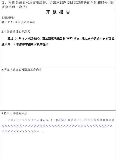
图1.从轮廓的形状
可选择性基于基础草图的造型系统包括轮廓的形状以及变形的步骤。从轮廓变形的步骤,如图1所示,(一),(二),(三),(四),然后用户在这些区域内勾画出轮廓,首先估算,然后转换为高度场,表面上的网格诞生了。用户不断素描轮廓和系统会生成新的网格因此将合二为一,以现有的表面,直到点击一个按钮,以明确到这一步。
在变形的每一步,介绍的四种形态的草图和素描的路线是可以区分出来的。第1个形状是一个上述的的轮廓相交确定的一个封闭区域,接着就是对区域的表面进行各种类型的操作。如果开始从里边区域和表面轮廓的外面的末端,挖空表面里面轮廓线的区域,如图2所示。
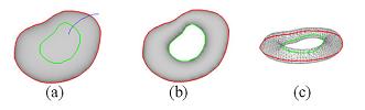
图2.定义的区域被挖空
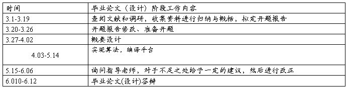
如果在这区域内,可以使这区域的表面凹或凸起。一旦该区域被确定,鼠标滚轮,可用于调整区域碰撞后的厚度面积,如图3所示,其中(b)和(c)显示旋转的角度观察而生成网格。
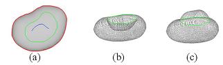
图3.做凹/凸的碰撞
该区域定义的形状与部分的轮廓可以相交,来对区域进行处理。当同一形状如图3在应用时,鼠标滚轮的滚动对厚度面积紧缩或胀大,如图4,而(b)和(c)显示在一个旋转视角。

图4.紧缩或胀大处理
第2个是一个耳朵样的形状开始和结束都在内部的等高线,并覆盖外面的一部分。如图5所显示,这一形态被解释为变形弧在两个等高线的交叉点之间的融合和生成一种新的表面对应变形轮廓线。
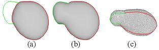
图5.对耳形态处理
第3个是一个草图开始和结束都在外面的等高线,隔开轮廓线分成两部分。如图6所示,切割表面的一部分。
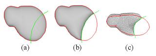
图6,切割处理
最后形态包括二个连续剪影。第一个是在等高之内的开放剪影,而第二个是在第一个开放剪影附近轮廓。如图7所示的结果,两个剪影代表参考和弯曲变形的目标曲线。
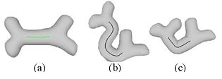
图7,弯曲处理
我们的系统所介绍的变形方法类似于Teddy,但是,如何实现和执行的思想是大大不同于Teddy。我们在以下部分将详细阐明算法。
3.轮廓成形的方法
如第3部分描述,一旦等高线被素描出来,距离场的区域可以根据等高线估计算出来,其中它的沿等高线剪影的最近点取决于等高线里面每点距离值。领域内的文献有不少方法来计算距离,不过,他们大多数是相当慢。在我们的系统采取的距离变革方法,需要较少的计算和记忆。在谈到[1],距离场的计算分在以下几个步骤。我们从四个角落通过扫描包围盒的轮廓获得4个临时距离图,转化为实地距离,为初步填充范围内的轮廓,分别称为ILB,IRB,ILT和IRT. 等高点和外部点的距离值是由一些可区分的值并可以跳跃的估算。只有内部点的距离点是需要计算的。当前点的距离值是指明为行和列两个值之间取较小的然后加1。这体现在以下公式:
ILB(x, y) = min(I0(x-1,y),I0(x, y-1)) + 1 (1)
IRB(x, y) = min(I0(x+1,y),I0(x, y-1)) + 1 (2)
ILT(x, y) = min(I0(x-1,y),I0(x, y+1)) + 1 (3)
IRT(x, y) = min(I0(x+1,y),I0(x, y+1)) + 1 (4)
生成ILB,IRB,ILT和IRT 距离图示8(一)(二)(三)及(四)。
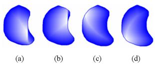
图8.从4个角落计算临时距离
在四张距离图对应的值中通过选择每点的最小值,所显示在下列公式:
I = min(ILB,IRB,ILT,IRT) (5)
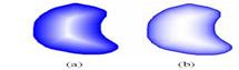
图9.距离场和高度场
平滑的过程适用于距离现场,来消除人为地脊线作用。在我们的系统中,一个高斯模糊应用,图9 (一)展示平滑距离场。图9 (二)从距离场显示高领域转化,该叙述如下。
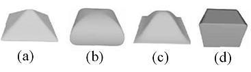
图10.不同模型在不同领域的作用
如图10所显示,我们试验通过使用在我们的系统的不同的作用变换距离到高度领域。我们测试了在我们的系统下变革并得到等高线内的不同形状 。图10 (a)采用线性变换;图10 (b)使用的整数变换;图10 (c)利用正弦函数,图10 (d)使用一个二元函数。
用户可以选择其中的变换函数,以产生理想的高度场 。如图10(b)所示圆形的转变是由我们系统提供的默认转变。其他形状的可通过点击其他的图标界面。由于这是一个新的简单性的变换函数,更多有用的形状可以很容易的发现和应用,来可扩大在系统内支持造型。
至于目前的执行情况,在一个用户定义的密度进行高度场采样,再转换为三维顶点,然后连接到建立三角网格。对于在高度场的内部区域上的每点,两个平面对称的顶点以形成一个封闭的网格。
内部端点的拓扑结构可以很容易地被建立在共同的高度领域,由于等高线通常不是规则形状,如图11所示对原始的等高线进行重采样建立合格的滤网。轮廓附近的网格点和轮廓线交叉点的网格点被收集,像图11所显示被环绕的点和绿色的点。当从高度领域建立三角形网格时,每个拓扑的环绕点都被绿色的点替换。
如上所述,滤网的确立可以取决于指定高度领域的采样密度。图12所示的一个例子,网格的构建根据不同的决议,等高线将重采样一次,不同的采样密度是以保证剖分均匀的网格。数值参数的取样密度可以用滚动鼠标滚轮来控制,绘制草图就相对容易。
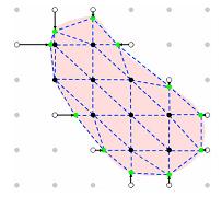
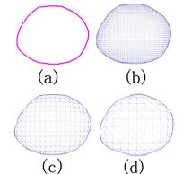
图11.高度场的三角剖分 图12.不同网格的取决
4.基于草图的变形
在第三部分的描述中,四类型形态和他们的功能基于草图的建模系统中。由于清楚每手势的类型的定义,一个草图的绘制可能很容易被认可。我们将在下列段落方面解释每个手势的功能的实施细节。
一旦区域的姿态的说明被定义,系统会等待一个有效的次级姿态确定对这区域进行操作。如果次级姿态是象在图2显示的那个的剪影,额外的等高线首先被创造。距离领域、高度领域和滤网然后重新计算在二等高之间生产在表面的凹陷。
如果次级形态像图3显示的剪影,在经由选择的高度内才能进行操作。降低高度,意味要创造一个凹的颠簸表面,而增加意味创造一个凸的颠簸表面。举例来说,当用户滚动鼠标滚轮,在该区域每个点的高度值的改变根据它的距离将改变到区域等高。如图4所示的姿态,除在表面上夸大或者压低的对称性默认的情况外,几乎和图3用的相同的方式。
一旦耳朵样的形态它被确定为如图5所示的等高成长的运行,在我们目前的执行两弧之间的交叉融合,对原有的轮廓进行变形,来配合这一形态的素描。创建新的网格,来反应轮廓变形。该函数的形态能够尽快落实,以包括小组形态以及第二形态,使原来的表面可以用来确定如何在耳形区合并。该类型的小组形态是指在一个类似表示,在该小组的姿态界定在该地区的清晰度的姿态。素描即位于该区域表明,在原表面以保持原来的弧形,形成了新的封闭区域,并产生一个网状的表面,以合并。表面上文所述,在原表面素描这点以外的区域,显示的方式合并。两者之间的差别是前者在表面所产生的明显的域。
一旦切割的姿态,它确定轮廓通货紧缩的运作,如图6所示,两弧之间的交叉融合,是取代素描,在两者之间。新的网格,然后创造,以反映轮廓变形。
一旦弯曲姿势及其分姿态已定,它们被认为是作为参考曲线与目标曲线的弯曲变形。
两个面垂直于参考曲线的起点和终点,把网格分为三个部分:(一)静态区域-从该区域开始切割,目标曲线是不会改变的(二)可变形区域-在两切削平面,变形和目标曲线(三)刚性的区域-在底切割面区域,这就是硬性的形变和目标曲线 。
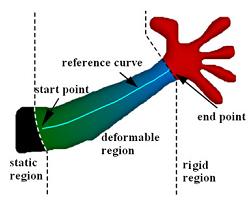
图表13显示如何划分区域的网格。
在变形区域相应来往的所有顶点,并沿参考曲线或曲线的目标应建立在弯曲运行。我们分配一个值,以每一个顶点,这是归一弧长从起点到终点。值介于0和1 ,其中s = 0表明,一开始就点和S = 1 ,表明结束点。我们指派商S = 0的所有顶点在静态区域,并指派= 1至所有顶点在刚性区域。
每个顶点分配一个S值,以对应与参考曲线与目标曲线,改造每一个网格顶点在变形区域,是由转型,其对应的顶点在参考曲线对应顶点在目标曲线,如图所示14 。
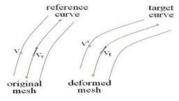
图14
一旦我们在计算目标位置和理想的旋转角度θ ( v )的一个顶点,我想最后的变形位置第五顶点
v= v = T (vt)R(θ(v))T (?vr)v
5.实验结果
我们的系统能营造自由模式,不用键入数值参数使电脑和用户交互式的能完成建模工作,字任何数值参数(除滚动鼠标滚轮调整厚度的选定区)。第一栏的图15显示建模过程中的一条鱼几乎很少。在不同的角度,其他三栏显示模式,。一旦轮廓该鱼是勾画出时,系统会产生一个模型如图一所示15。用户写生,以选择一个区域为操纵;则可以调整厚度的区域在图15(e)。用户写生,以选择其他区域;调整这些区域通过调整厚度面积如图一所示 15
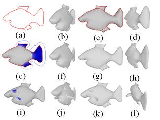
图15
我们认为,在我们的系统中,允许对更复杂的轮廓建模和变形,所以系统的状况大大改观。
6. 结论和以后工作
在这篇文章中我们已经提出了一个基于草图的造型的方法。在该系统中,用户是能够创造出比较复杂的网格几乎只有素描的投入,这使得建立一个三维模型,非常直观和有效率。除了由一种新的推理方法为形状,从轮廓问题,我们也确定了一套基于草图的手势,以修改模型表面方便。该系统的运行速度互动利率标准的个人电脑。整个系统更加适应非专家用户。 所提出的方法请了很多未来的改善。 (一)在进一步的研究中,我们要发展一个系统,使更复杂的拓扑结构。(二)更手势可能被引入到这一服务系统,以实现其他有用的行动对网格。(三)现行制度提供了相同形状的推理方法,为各类轮廓,但它并不总是给一个理想的结果。我们可以结合了素描识别方法和基于模板的建模方法,把该系统扩展到获得更理想的结果,在更迅速的方式。
外文原稿
An adaptable sketch-based modeling system
Abstract:
In this paper, we propose a novel approach for inferring a closed smooth surface fromsketched contours and deforming it by the following sketch-based gestures. Once the contours are drawn, smooth distance ?elds are computedwithin the contours, which are then transformed into height ?elds. A closed smooth surface is obtained upon the contours and the inferred height ?elds. The smooth surface can be further deformed by the four deformation gestures de?ned in the system. Though simple in idea, the system is able to create moderately complex models very quickly and intuitively.
1.Introduction
Sketches are hand-drawn images using rough, wobbly strokes, usually capturing only the essential parts and properties of the 3D object. The acceptable imperfection and simpli?cation allows the designer to draw the sketches very quickly and effectively. Since sketching is a very natural process that allows a user to draw what he or she is thinking of directly, sketch-based modeling holds the promise of making the design process faster and more intuitive and thus making 3D modeling accessible to a signi?cantly wider audience than current modeling tools. In this paper, we present a modeling environment which allows the user to sketch simple 3D freeform objects. In literature on modeling, there are few systems based directly on sketches. Different viewers may make different inferences about complicated contour sets. Thus the best thing can hope for is to create plausible shapes for a fairly large class of contours on which users agree on the interpretation. Teddy system is a good research step into this problem, but limited to simple closed curve contours. Our work extends the idea of Teddy substantially in the following aspects: ?rst, it allows drawing arbitrary topology of the contour strokes rather than a simple closed contour; second, it provides several choices for the user to decide the shape of the contour interior; third,more editing operations are introduced to perform modifications; fourth, it produces more well-formed mesh, for example, triangulates more uniformly and avoids elongated triangles; lastly, the algorithm is more robust in that it seldom fails to give a reasonable result. It is natural to design a sketching interface to let the user and the computer share the work, each doing what it does best. Our system first takes a user’s contour-sketch of a smooth surface and ?nds a 3D surface whose contours ?t the collection of contours that the user drew. The system then recognizes the different gestures drawn over or around the generated surface to perform modifications. All the editing results are exhibited to the user at interactive rates. Though simple in manipulation, however, the created models still lack of accuracy and are more applicable to prototyping.
2.The sketch-based modeling process
The adaptable sketch-based modeling system consists of a shape-from-contour step and a deformation step. At the shape-from-contour step, as shown in figure 1 (a) (b) (c) and (d), a distance field within the user sketched contour is first computed and then converted into a height ?eld, upon which the surface mesh is created. The user keeps sketching contours and the system generates new meshes accordingly to be merged to the existing surface until he or she clicks on a button to explicitly break this step.
At the deformation step, four types of gestures are introduced, each with a distinguishable sketch path. The ?rst gesture is a closed sketch that intersects with the aforementioned contour that de?nes an area, followed with a sub-gesture to de?ne the types of operation on the area over the surface. If the sub-gesture starts from inside of the area and ends outside of the surface contour, it is meant to hollow out the surface of this area, as shown in ?gure 2.
If the sub-gesture lies within the area, it is meant to makea concave or a convex bump on the surface at this area. Once the area is determined, mouse wheel may be used to tune numerically the thickness of the area to make the bump,as shown in ?gure 3, where (b) and (c) show the resultant meshes at a rotated view.
The area de?nition gesture can also intersect with part of the contour to de?ne an area for manipulation. When the same sub-gesture used in ?gure 3 is applied, the rolling of mouse wheel that still changes the thickness of the area will result in a de?ation or in?ation of the area, as shown in ?gure 4, where (b) and (c) are shown in a rotated view angle.
The second gesture is an ear-like gesture that starts and ends at inside of the contour and covers an outside portion.The gesture is interpreted as deforming the arc between the two intersections at the contour to match the gesture sketch and generating a new surface to correspond to the deformed contour, as shown in figure 5.
The third gesture is a sketch that starts and ends both at outside of the contour, which separates the contour into two portions. The gesture is interpreted as cutting the right portion of the surface, as shown in ?gure 6.
The last gesture consists of two sequential sketches. The first sketch is an open sketch within the contour, while the second is an open sketch near the ?rst. The two sketches represent the reference and the target curve for a bending deformation. The result is as shown in figure 7.
The deformation methods introduced in our system are somehow similar to that of Teddy; however, the idea of how to realize them and the performance is substantially different from that of Teddy. We will illuminate the algorithm in detail in the following sections.
3. Shape-from-contour approach
As described in section 3, once a contour is sketched, a distance ?eld is computed within the contour, where the distance value of each point inside the contour is determined by ?nding its nearest point along the contour sketch. There are quite many approaches for computing the distance field in the literature; however, most of them are quite slow. The distance transformation method [1], which requires less computation and memory, is adopted in our system. Referring to [1], the distance ?eld can be computed in the following steps. We first obtain four temporary distance maps by scanning the bounding-box of the contour from the four corners, where each pass returns with an individual transformed distance ?eld for the initial ?ood-?lled area within the contour, called ILB , IRB,ILT and IRT respectively. The distance values of the contour points and the exterior points are prede?ned by some distinguishable values and can be skipped in the computation. Only the distance values of the interior points need to be calculated. The distance value of the current point is speci?ed as one plus the smaller value of the two previously visited adjacent points in row and column, as shown in the following formulae:
ILB(x, y) = min(I0(x ? 1, y), I0(x, y ? 1)) + 1 (1)
IRB(x, y) = min(I0(x + 1, y), I0(x, y ? 1)) + 1 (2)
ILT(x, y) = min(I0(x ? 1, y), I0(x, y + 1)) + 1 (3)
IRT (x, y) = min(I0(x + 1, y), I0(x, y + 1)) + 1 (4)
The generated ILB, IRB, ILT and IRT distance maps are shown in figure 8 (a) (b) (c) and (d) respectively.
The distance ?eld is then obtained by choosing the minimum value for each point among the four corresponding values in the four distance maps, as shown in the following formula:
I = min(ILB, IRB, ILT, IRT) (5)
A smoothing process is applied to the distance ?eld to remove the arti?cial ridge line effect in the distance ?eld. In our system, a 3 by 3 Gaussian blurring is applied. Figure 9 (a) shows the smoothed distance ?eld. Figure 9 (b) shows the height ?eld transformed from the distance field, which will be described below.
We experiment by using different functions in our system to transform the distance ?eld to the height field, as shown in ?gure 10. We have tested in our system the following transformation functions and get different shapes within the contour. Figure 10(a) uses a linear transformation; ?gure 10(b) uses a rounded transformation; ?gure 10(c) uses a sine function; while ?gure 10(d) uses a binary function.
User can select one of these transformation functions to generate a desired height ?eld. The round transformation as shown in ?gure 10(b) is the default transformation provided by our system; the other shapes can be obtained by clicking on some extra icons in the interface. Due to the simplicity of applying a new transformation function, more useful shapes can be easily discovered and applied to extend the supported model classes in the system.
For the current implementation, the height ?eld is sampled at a user de?ned density and then converted to 3D vertices, which are then connected to build the triangular mesh. For each point in the interior region of the height ?eld, two symmetric vertices on both sides of the view plane are created in order to form a closed mesh.
The topology of the interior vertices can be easily built in the way like common height ?eld. Since the contour is usually not regular-shaped, we re-sample the original contour as shown in ?gure 11 to build a well-formed mesh. Both the grid points adjacent to the contour and the intersections of the grids and the contour are collected, such as the circled points and the green points shown in ?gure 11. Each circled point is replaced by its correspondence green points in topology when building the triangular mesh from the height field.
As described above, the resolution of the mesh can be determined by specifying the sampling density of the height field. Figure 12 shows an example of the created meshes at different resolution. The contour will be re-sampled once a different sampling density is speci?ed, to ensure the uniformity of the mesh triangulation. The numerical parameter of the sampling density can be speci?ed by rolling the mouse wheel, which is as easy as drawing sketches.
4. Sketch-based deformation
As described in section 3, four types of gestures and their functions are de?ned in the sketch-based modeling system. Due to the clear de?nition of each type of gesture, it can be easily recognized once a sketch is drawn. We will explain the implementation detail for the function of each gesture in the following paragraphs.
Once the gesture that de?nes an area is speci?ed, the system waits for a valid sub-gesture to determine the operation on the area. If the sub-gesture is a sketch like the one shown in ?gure 2, an extra contour is ?rst created. The distance ?eld, the height ?eld and the mesh are then recomputed between the two contours to produce the hollow on the surface.
If the sub-gesture is a sketch like the one shown in ?gure 3, the height values within the selected area are to be manipulated. Decreasing the height values means to create a concave bump at the area, while increasing the values means to create a convex bump. For example, when the user rolls the mouse wheel, the height value of each point within the area will change depending on its distance to the area contour. The sub-gesture shown in ?gure 4 is implemented almost in the same way as in ?gure 3, except that the both sides at this area on the surface in?ate or de?ate symmetrically by default in the case.
Once the ear-like gesture that de?nes the contour-growing operation as shown in ?gure 5 is determined, in our current implementation the arc between the two intersections on the original contour is ?rst deformed to match the gesture sketch. The new mesh is then created to re?ect the contour deformation. The function of this gesture can be implemented to include a sub-gesture as well, where the second gesture could be used to de?ne how the ear-shaped region is merged to the original surface. The types of the sub-gesture are de?ned in a way similar to that of the sub-gesture de?ned in the area-de?nition gesture. The sketch
that lies within the area indicates to keep the original arc to form a new closed region and to generate a mesh surface to be merged to the original surface. The sketch that points outside of the area indicates the way of merging surface described above. The difference between the two sub-gestures is that the former generates a distinct valley between the two surfaces.
Once the cutting gesture that de?nes contour de?ation operation is determined, as shown in ?gure 6, the arc between the two intersections are replaced by the sketch in between. The new mesh is then created to re?ect the contour deformation.
Once the bending gesture and its sub-gesture are determined, they are considered as the reference curve and the target curve for the bending deformation.
The two planes that are perpendicular to the reference curve at the start point and the end point cut the whole mesh into three parts: (a) the static region - the region out of the start cutting plane, which will not change with the target curve; (b) the deformable region - the region between the two cutting planes, which will be deformed with the target curve; (c) the rigid region - the region out of the end cutting plane, which will be rigidly deformed with the target curve.Figure 13 shows how to partition the regions of the mesh.
The correspondence between all the vertices in the deformable region and those along the reference curve or the target curve should be established before the bending operation can be performed. We assign a value S to each vertex, which is the normalized arc length from the start point to the end point. The value ranges between 0 and 1, where S = 0 indicates the start points and S = 1 indicates the end points. We assign S=0 to all the vertices in the static region, and assign S=1 to all the vertices in the rigid region. With each vertex assigned an S value to correspond with the reference curve and the target curve, the transformation of each mesh vertex in the deformable region is determined by the transformation of its correspondence vertex in the reference curve to the correspondence vertex in the target curve, as shown in figure 14.
Once we have computed the target position and the desired rotational angle θ(v) for a vertex, the ?nal deformed position v of the vertex v will be
v = T (vt)R(θ(v))T (?vr)v (6)
where T indicates translation and R indicates rotation about the normal of the sketch plane and θ(v) is computed the same way as in [7].
5. Experimental results
Our system can create freeform models on a standard PC at interactive rates and user can ?nish his modeling work in several minutes without typing any numerical parameters (except for rolling the mouse wheel to adjust the thickness of the selected areas). The ?rst column of ?gure 15 shows a modeling process of a ?sh with very few strokes. The other three columns show the model in different views. Once the contour of the ?sh is sketched, the system will generate a model as shown in ?gure 15(b). User sketches to select a region for manipulation; then adjusts the thickness of the region as in ?gure 15(e). User sketches to select other regions; adjusts these regions by tuning the thickness of the area as shown in Figure 15(i).
6. Conclusions and future work
In this paper we have presented an approach for sketch-based modeling. In the system, users are able to create rather complicated mesh with almost only sketch input, which makes the creation of a 3Dmodelvery intuitive and ef?cient. Apart from de?ning a novel inference approach for the shape-from-contour problem, we also de?ne a set of sketch-based gestures to modify the model surface conveniently. The system runs at interactive rates on a standard PC. The whole system is more adapt to non-expert users. The proposed method requests a lot of future improvements.(a) In the further study, we want to develop a system that allows more complex topologies. (b) More gestures may
be introduced into the system to realize other useful operations on the mesh. (c) The current system provides the same shape inference approach for all kinds of contours; however,it does not always give a desirable result. We may combine a sketch recognition approach and a template based modeling approach to extend the system to obtain more desirable results in a more rapid way.
References
[1] G. Borgefors. Distance transformations in arbitrary dimen-sions. In Proc. of Computer Vision, Graphics, and Image Processing, 27(3):321–345, 1984.
[2] D. Bourguignon, M.-P. Cani, and G. Drettakis. Drawing for illustration and annotation in 3d. Computer Graphics Forum, 20(3):114–122, 2001.
[3] J. M. Cohen, L. Markosian, R. C. Zeleznik, J. F. Hughes, and R. Barzel. An interface for sketching 3d curves. In ACM Symposium on Interactive 3D Graphics, pages 17–22, April 1999.
[4] T. Igarashi, S. Matsuoka, and H. Tanaka. Teddy: A sketch- ing interface for 3d freeform design. In Proceedings of SIGGRAPH 1999, pages 409–416, July 1999.
[5] S. F. Johnson. Lumo: illumination for cel animation. In Proceedings of the Symposium on Non-photorealistic animation and rendering, pages 45–52, 2002.
[6] O. Karpenko, J. F. Hughes, and R. Raskar. Freeform sketching with variational implicit surfaces. Computer Graphics Forum, 21(3):585–594, Not yet known 2002.
[7] Y. Kho and M. Garland. Sketching mesh deformations. In Symposium on Interactive 3D Graphics and Games, pages 147–154, 2005.
[8] H. Lipson and M. Shpitalni. Conceptual design and analysis by sketching. AIEDAM-97, 14:391–401, January 1997.
[9] A. Nealen, O. Sorkine, M. Alexa, and D. Cohen-Or. A sketch-based interface for detail-preserving mesh editing. ACM Transactions on Graphics, 24(3):1142–1147, 2005.
[10] J. P. Pereira, V. A. Branco, J. A. Jorge, N. F. Silva, T. D. Cardoso, and F. N. Ferreira. Cascading recognizers for ambiguous calligraphic interaction. In Eurographics Workshop on Sketch-Based Interfaces and Modeling, pages 63–72, 2004.
[11] K. H. R.C. Zeleznik and J. Hughes. Sketch: An interface for sketching 3d scenes. In Proc. SIGGRAPH, pages 163–170, August 1996.
[12] K. N. T. I. S. Owads, F. Nielsen. A sketching interface for modeling the internal structures of 3d shapes. In Proceedings of Third International Symposium on Smart Graphics, pages 49–57, 2003.
[13] A. Shesh and B. Cohen. Smartpaper: An interactive and user-friendly sketching system. Computer Graphics Forum,23(3):301–310, August.
[14] Sketchup. Sketchup software: 3d sketching software for the conceptual phases of design. http://www.sketchup.com.
[15] O. Tolba, J. Dorsey, and L. McMillan. A projective drawing system. In ACM Symposium on Interactive 3D Graphics,
pages 25–34, April 2001.