机械原理课程设计
——吊车臂的机构设计分析
 指导老师:***
所在班级:***
组 员:***
日 期:二○##年六月
目 录
一、目的与意义............................................3
二、吊车作用..............................................4
三、设计计算..............................................4
四、受力情况..............................................5
五、分析计算..............................................6
六、心得体会..............................................8
附件:工模全图
一、目的与意义
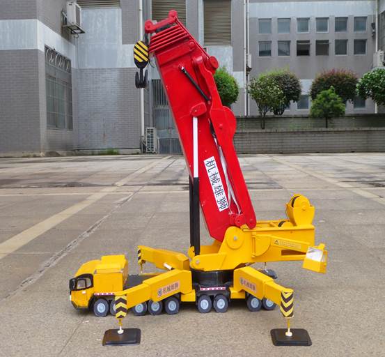 物流活动中的装卸和搬运涉及的是货物在生产和流通过程中短距离的空间位移,是现代物流系统的技术支撑要求之一,手动液压吊车对提高物流能力与效率,降低物流成本,保证物流质量等方面都有着非常重要的作用。手动液压吊车以手动油泵作为动力源,在单个人力操作下能将重物吊起,并运送一定距离或转移一定方位放下来,搬运过程机动灵活,因此被广泛应用于中小企业、高校和研究院所。手动液压吊车对提高物资流通中的装卸、搬运效率有着很大的实用价值。因此,我们结合老师上课所讲,以及工程模型设计制作大赛,开展了此次机构设计分析的设计研究。
二、吊车作用
1、节约劳动力,减轻装卸搬运工人的劳动强度,改善劳动条件;
2、缩短作业时间,加速车辆周转,加快货物的发送和发出,从而提高效率;
3、提高装卸搬运质量,保证货物的完整和运输的安全;
4、提高作业效率,减低作业成本;
5、可以在很小的地面和空间内完成较大的起重运输任务;
6、机动、灵活、幅度长、起重量大、行驶速度快。
三、设计计算
1、 机构运动原理的设计
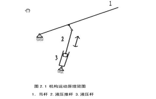
(1) 机构运动原理简图
(2)自由度计算
图 2.1 中的机构运动原理简图中,含 3 个活动机构,4 个低副。
自由度数为:F=3*3-2*4=1
原动件数为 1,原动件数目等于机构自由度数,所示机构具有确定的运动。
四、受力情况
1、 各级工作吊杆长度的确定及其乘载能力的计算
吊杆如下图所示:
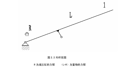
(1)吊杆简图 R 为液压缸的力臂 (LR)为重物的力臂 按实际工作要求及起重货物的大小,初取 R400mm。
(2)按实际工作要求及起重货物的大小,初取 L900mm。
(3)吊车工作时能受的最大载荷为要求的 0.35 吨,m350kg。
五、分析计算
1、确定吊杆摆动角度。
按实际工作要求取吊杆摆动的最大角度初取为 60°。
要考虑车身与物件的高度。
初取最低位置与水平线夹角为-35°。
初取最高位置与水平线夹角为 25°。
所以,最大垂直摆距为:
D=(R+L1)(sin35°sin35°) (2.1)
=(400+900)(sin35+sin25°)
=1300*(0.5735+0.422)
=1 245mm
由实际工作要求取吊钩的最低位置距地面不大于 500mm,吊钩的最高位置 1500mm, 所以最大垂直摆距在 1000mm 到 1500mm 之间,(2.1)式结果符合。
吊杆到吊钩之间的吊臂取 H=1200mm。
所以,支架高: H=1500-D+(R+L)sin35+H1 (2.2)
=1500-1245+1300*sin35+200
=1200mm
按实际工作要求,一般吊杆由最低位置升起较短的一段距离后,才受到重物的重力作用,取该时吊杆摆过的角度为:15°。
因为,M=Fdsinα(α为重力与吊杆的夹角)。
该位置取液压杆与吊杆垂直,使得获得最大力矩,从而较易吊起重物。
液压缸的最长状态为:L11056mm。 最短状态为:L0572mm。 所以,推程为:
S=L1-L0 (2.3)
=1056-572
= 484mm
取推程为:S500mm。
进行受力分析有: T* Rsinβ=G(R+L)sinα (2.4)
(β为液压推力 T 与吊杆的夹角)
所以: T=(sinα/ sinβ) *G(R+Lx)/R (2.5)
得各位置的数据如下表:
表 2.1 吊杆各位置角度及其正弦比关系表
 所以:
所以:
T=(sinα/ sinβ)*G(R+L)/R (2.6)
=1.15 *350* 9.8 *(400+900)/400
=13377N
取阻力系数 k=0.35(含吊杆自重与摩擦力)
所以: F=T(1+k) (2.7)
=13377*(1+0.35)
=18060N
六、心得体会
经此次机械原理课程设计,参考自我们工程模型大赛的作品。在分析和制作中,我们都懂得和认知到了自己的很大的不足。不管是设计方案还是设计那些机构,还有数字计算等,我们都欠缺的很多,都还有很多的空洞未能补上,都还需要我们花费很多的时间去填补和获取。虽然说我们学的只是理论但我们要实现的确是实践。可能一开始因为大家的理论不足和实践的经验不足都可能够造成我们在设计过程中存在不少的麻烦,但我们坚信实践是能出真理的只要我们能更好的学好课堂上的理论知识。通过该项目加强了我们工程实践能力、创新意识,激发了我们进行科学研究与探索的兴趣,充分挖掘了我们的创新潜能与智慧,既提高了我们学生科研创新能力,又提高了我们实际动手能力。
虽然此次做出的只是模型,相信在不久的将来我们就能实践出我们自己的真理 ,做出真正的液压吊车。

第二篇:起重机的设计
Hoist mechanism

A hoist mechanism for lifting a load includes a hollow support post, a threaded spindle rotatably mounted within the post, a traveling nut carried by the spindle for movement therealong during rotation of the spindle, a carriage engaged by the traveling nut to move along the spindle, and a motor for effecting rotation of the spindle. The post has a longitudinal opening aligned with the spindle having a width permitting the spindle to be moved laterally therethrough. The spindle is releasably connected to the motor drive shaft at one end and to a support bearing at the other end. Lift arms for supporting a load are connected to the carriage through the post opening. The hoist mechanism also includes a clutch mechanism providing a braking force during lowering and a

safety switch assembly for terminating operation whenever the lift arms are blocked.
The invention relates generally to a hoist mechanism and, more particularly, to a jacking device for lifting heavy loads including a hollow post, a threaded spindle rotatably supported within the post, a traveling nut carried by the spindle and a load-bearing carriage mounted within the post and moved along the spindle by the traveling nut.
Lift jacks for trucks and other vehicles employing a sliding carriage supported by a traveling nut are known in the art. In prior art constructions, removal of the threaded spindle, which is usually driven by a motor through gearing at its upper end and supported by a bearing at its lower end, usually required trained personnel and a considerable expenditure of time. Consequently, replacement of the spindle because of wear was extremely costly.
It is therefore an object of the invention to provide a hoist mechanism, particularly a lifting device, of the type described which can be simply and quickly disassembled.
In accordance with the invention, a hoist mechanism includes an upright, hollow support post having a longitudinal opening through the side thereof, a threaded spindle rotatably mounted within the post aligned with the opening, a traveling nut engaged by the threaded spindle for linear movement therealong, a sliding carriage within the post moved by the traveling nut and a motor for effecting rotation of the threaded spindle. Aligned openings in the post and the carriage having a diameter greater than the diameter of the threaded spindle and the traveling nut permit both the threaded spindle and the traveling nut to be removed laterally through the opening in the support post when the threaded spindle is disconnected from its support.
With such a design, it is relatively easy to remove the threaded spindle and the traveling nut, since there is no need to remove the movable carriage, which is simply supported by the traveling nut. Easily releasable mountings for the threaded spindle on the drive unit and on the lower bearing are provided so that the threaded spindle may be changed in approximately 10 minutes, whereas the known types of construction often required 10 hours.
In the hoist mechanism herein, an external plate is disposed outside the support post and is removably connected to the carriage through the opening in the support post. The external plate can be designed as the load-bearing device or configured to enable attachment of a suitable load-bearing device, such as spaced lift arms. The lift arms for supporting a load to be lifted are attached to the external plate or, alternatively, secured directly to the carriage through the post opening, thereby eliminating the need for the external plate. The external plate can be advantageously constructed so that different load-bearing devices can be optionally attached to fulfill specific requirements. To provide stability, the external plate is configured to partially surround the support post. When the external plate or the lift arms are removed, the post opening is rendered accessible permitting removal of the threaded spindle therethrough.
In an exemplary embodiment, the external plate is provided with two slits at a distance from each other which extend transversely to the support post along the longitudinal opening so that a cover strip may be passed through the slits to cover the ope side of the support post and protect the threaded spindle and the traveling nut against damage and accumulation of dirt and the like.
The threaded spindle is joined to a coaxial motor drive shaft by an easily removable coupling. The threaded spindle and the drive shaft each have a flange formed at their adjoining ends with both flanges being held together by an axially split coupling sleeve. The axially split coupling permits disconnection and connection of the parts in a relatively short time. Further, the coupling allows the two flanges to be axially spaced apart so that the threaded spindle may be moved axially toward the drive shaft permitting easy removal of the threaded spindle from the bearing supporting its lower end.
In order to facilitate lateral removal and installation of the threaded spindle, the lower end of the threaded spindle, which is opposite the drive end, is radially supported by a bearing flexibly mounted. The flexible mounting allows the threaded spindle to be tilted slightly while it is within the bearing and thereafter withdrawn in an axial direction. An axially-split mounting may be provided for the lower bearing of the threaded spindle so that the threaded spindle and the lower bearing can both be removed laterally from the support post, if necessary.
According to a further exemplary embodiment of the invention, the threaded spindle or the motor shaft is provided with a one-way clutch which is engaged whenever the threaded spindle is rotated to lower the movable carriage. The weight of the motor and the load exerted on the threaded spindle through the traveling nut acts in an axial direction on the clutch. The clutch, in turn, is axially supported on a friction surface so that when the clutch is engaged, increased frictional force is applied to the threaded spindle to provide a braking force during lowering of a load. As a result, the traveling nut can be a frictionless nut thereby increasing operating efficiency.
According to another advantageous embodiment of the invention, means are provided to terminate operation of the hoist mechanism when movement of the carriage or lift arms is blocked. Attached to the movable carriage is an actuating element which, in turn, is mounted on a draw rod or a cable so that relative displacement between the carriage and the traveling nut causes the traveling nut or a following locknut to operate the actuating element so that the draw rod or the cable is moved. Movement of the draw rod or the cable activates a switch which cuts off the motor. Such a safety device is necessary to prevent hazardous operation whenever the movement of the carriage is blocked by a misplaced object under a lift arm .
FIG. 1 is a fragmentary, exploded cross-sectional view of a hoist mechanism constructed according to the invention illustrating the configuration and arrangement of the support post and the movable carriage therein;
FIG. 2 is a fragmentary longitudinal cross-sectional view of the hoist mechanism illustrating the configuration and arrangement of the movable carriage, the threaded spindle and the traveling nut;
FIG. 3 is a lateral and a horizontal cross-sectional view showing a coupler for connecting the rotatable threaded spindle with the drive shaft;
FIG. 4 is a fragmentary longitudinal cross-sectional view through the motor housing illustrating the details of the motor mounting;
FIG. 5 is a fragmentary schematic view of a safety device for the hoist mechanism installed on the movable carriage; and
FIG. 6 shows a side elevational view of the hoist mechanism illustrating the entire configuration thereof.
The overall configuration of the hoist mechanism is seen in FIG. 6.
Referring to FIGS. 1 and 2, an illustrative embodiment of the invention is shown. A hollow, elongate, upright support post 1 having a U-shaped cross section includes lateral side walls of equal length with inwardly projecting edge segments 2 defining a longitudinally extending forward opening. Disposed within the support post 1 is a U-shaped movable carriage 4 having three spaced apart, generally U-shaped horizontal plates 5 secured between the walls thereof. The carriage 4 is disposed within the support post 1 so that the forward opening of the carriage 4 defined partially by the U-shaped plates 5 is substantially aligned with the forward opening in the support post 1.
Rotatably secured to the carriage 4 are guide rollers 3, which engage the inner surfaces of the edge segments 2 and the other side walls of the support post 1 to maintain the carriage 4 in proper alignment within the support post 1 and provide smooth movement therebetween.
A threaded spindle 6 is rotatably mounted within the support post 1 and is generally aligned with the forward opening in the support post 1. A traveling nut 7 is carried by the threaded spindle 6 for linear movement therealong in response to rotation of the threaded spindle 6. The diameter of the threaded spindle 6 and the traveling nut 7 is less than the width of the forward opening of the support post 1 or the carriage 4 so that the threaded spindle 6 and traveling nut 7 may be inserted into or removed from the support post 1 or carriage 4. The legs 8 of the U-shaped plates 5 are spaced apart at a distance greater than the diameter of the spindle 6 so that the spindle 6 may be moved therethrough, as indicated by the arrow in FIG. 1. However, the legs 8 are spaced apart at a distance less than the diameter of the traveling nut 7 so that the traveling nut 7 engages operatively one of the plates 5.
If the threaded spindle 6 is rotated on its elongate axis counterclockwise, for example, the traveling nut 7 will move along the spindle threads upwardly. If the threaded spindle 6 is rotated counterclockwise, the threaded nut 7 will move downwardly. As seen in FIG. 2, the carriage 4 will be moved upwardly when the traveling nut 7 is moved upwardly, since the carriage 4 rests on the traveling nut 7 via the undersurface of one of the U-shaped plates 5. Similarly, the carriage 4 will move downwardly as the traveling nut 7 moves downwardly. It should be evident that the traveling nut 7 is mounted with the carriage 4 so that it does not rotate relative thereto.
A generally upright external plate 10 is releasably secured to the legs 8 of the U-shaped plates 5 by bolts 9 which extend between the external plate 10 and the legs 8 through the forward opening of the support post 1. The external plate 10 is thereby movable relative to the outside of the support post via the movable carriage 4 inside of the support post 1. The external plate 10 is provided with a pair of horizontal brackets upon which a detachable lift arm, one of which is shown and designated 11, is pivotally secured to extend outwardly from the support post 1. It is evident, however, that the external plate 10 may be configured in any suitable manner to provide a means for engaging and supporting a load to be lifted. In FIG. 1, the external plate 10 is seen to have a width greater than that of the support post 1, while, in FIG. 2, the external pipe is seen to have a height greater than that of the carriage 4.
The external plate 10 has near its upper and lower edges a pair of spaced-apart slits 12 extending transversely to the support post 1. A cover strip 13 having a width substantially equal to the width of the support post 1 extends over the entire height of the support post 1 to cover the forward opening therein and has its upper and lower ends secured to the top and bottom of the support post 1, respectively. The cover strip 13 is threaded through the respective slits 12 so that it passes in front of the external plate 10 between the lift arms 11. The lateral edges of the slits 12 hold the cover strip 13 in alignment with the forward opening of the support post 1. Preferably, one end of the cover strip 13 is easily releasable from the support post so that it may be quickly removed during disassembly of the hoist mechanism.

?
?
?
?
?
?
? ?
?
?
?
?
?
?
?
?
?
?
?
?
?
?
?
?
?
?
?
?
? ?
?
?
?
?
?
?

A motor is provided for delivering power to rotate the threaded spindle 6. The motor is mounted at the upper end of the support post in a motor housing 22 (FIG. 6). The motor has a drive shaft 23 (FIG. 4) which is coaxially connected with the threaded spindle 6. As seen in FIG. 3, the drive shaft 23 and the threaded spindle 6 are releasably interconnected by a longitudinally split coupling sleeve 14. The threaded spindle 6 and the drive shaft 23 each have a radially extending flange at their adjoining coupling ends. The flange at the end of the threaded spindle 6 is designated 16 in FIG. 2. The coupling sleeve 14 has a recess 15 for receiving the flanges 16 and is secured about the flanges 16 by bolts 17 which lock the parts of the coupling sleeve 14 together. The driving force between the drive shaft 23 and the threaded spindle 6 is transmitted by friction from the drive shaft 23 through the coupling sleeve 14 to the threaded spindle 6. To facilitate easy insertion and removal of the threaded spindle 6, there is considerable play between the drive shaft 23 and the threaded spindle 6, as indicated by the space 18.
The axially split coupling 14 with tangentially engaged bolts 17 permits more rapid assembly and disassembly than would a flange coupling employing bolts running parallel to the spindle axis. It should be apparent that a positive connection could be utilized in place of the frictional connection provided by the coupling shown herein. Further, the drive shaft 23 may either be an extension of the motor shaft or the output shaft of a transmission driven indirectly by the motor.
The lower end of the threaded spindle 6 is rotatably supported at the base 21 of the support post 1 by a radial load ball bearing 19 providing a low friction mounting. The bearing 19 is, in turn, mounted to the base 21 by a resilient ring 20 made of rubber or the like. The resiliency of the ring 20 permits the bearing 19 and the threaded spindle 6 to be tilted so that the threaded spindle 6 may be easily removed or placed into the bearing 19.
Alternatively, the bearing 19 can be rigidly secured to the base 21. Removal of the threaded spindle 6 is then effected by moving the threaded spindle 6 directly upward out of the bearing 19. Thereafter, the threaded spindle 6 is removed laterally from the support post 1. This required that there be sufficient axial spacing between the threaded spindle 6 and the drive shaft 23 to permit adequate axial movement allowing removal. As a result, the distance 18 between the adjoining ends of the threaded spindle 6 and the drive shaft 23 will be somewhat greater than that illustrated in FIG. 3.
In an alternative construction, a split mounting for the bearing 19 similar to the coupling sleeve 14 may be used so that the bearing 19 may be removed laterally along with the threaded spindle 6 from the support post 1. Because of the shorter installation time, however, one of the previously-described forms of construction is preferred. In the case of a rather large space 18 between the adjoining ends in the coupling sleeve 14, a suitable spacer (not shown) can be inserted to prevent axial displacement of the threaded spindle 6 when the coupling sleeve 14 is assembled. This spacer can be designed to provide a positive junction between threaded spindle 6 and drive shaft 23. For example, diagonally-running grooves in the opposing flanges may cooperatively engage corresponding cooperating ribs on the spacer. Such a construction provides increased frictional contact within the coupler sleeve 14 or acts as a backup for the contact between the drive shaft 23 and the threaded spindle 6.
In FIG. 4, the motor housing 22, which is located at the upper end as an extension of the support post 1, is illustrated. For the purpose of simplicity, the motor is omitted and only its shaft 23 is shown. The motor shaft 23 is mounted within the housing 22 by radial load bearings 24. An axial load bearing 25 supports the weight of the motor and the load which is exerted on the threaded spindle 6. The axial bearing 25, in turn, is supported by a one-way clutch 26, which may be a free-wheeling cam and wedge construction. The clutch 26 is disengaged when the motor shaft 23 is rotated in one direction to lift the carriage 4 and its load, while it is engaged to turn with the motor shaft 23 when the motor shaft 23 is rotated in the other direction to lower the carriage 4 and
its load. The housing of the clutch 26 lies on a friction surface 27 which is designed so that the friction surface 27 and the clutch housing, when the clutch 26 is engaged, is sufficient to retard rotation of the threaded spindle 6 and provide automatic braking during lowering of the load. As a result, a frictionless nut, e.g., a ball bearing nut or a planetary roller nut, can be utilized as the traveling nut to obtain a corresponding increase in performance in the raising of the load. It should be evident that when the load is being raised, the clutch 26, is disengaged so that no braking force is generated between the clutch 26 and the friction surface 27 to retard rotation of the threaded spindle 6.
In the embodiment shown in FIG. 4, the friction surface 27 is disposed on a ring 28 which may consist of an appropriate material having a high friction coefficient. The ring 28 is stepped and has on the lower section, a friction facing 29 providing a safety feature. In the event abrasion wears away the friction surface 27 of the upper section, the clutch 26 rests on the friction facing 29 so that the load can no longer be moved downwards without substantial mechanical assistance.
The heat generated by friction in the thrust bearing 25 and between the clutch 26 and the friction surface 27 is dissipated by cooling fins 30, which are radially distributed completely around this section of the motor housing. The clutch 26 working with a friction surface may, of course, be located in other suitable positions, e.g., within the support post 1, but, preferably, the arrangement in the area of the motor housing is provided, since the heat produced can best be dissipated in this way.
Referring to FIG. 5, a safety device is installed on the carriage 4 which discontinues operation of the motor if, for example, the lift arm 11 is blocked by an out-of-place object whenever the load is being lowered. To accomplish this function, a projection 31 is provided on the carriage 4 and has an bore 32 through which a draw rod 33 installed in the support post 1 extends. The draw rod 33 operates a switch (not shown) provided in the area of the motor at the upper end of the support post 1 and thereby controls operation of the motor. During normal operation of the hoist
mechanism, the projection 31 slides along the draw rod 33 without engaging it.
Disposed in a recess in the projection 31 is a tilting element 34 which is provided with an aperture (not numbered) through which the draw rod 33 extends. The tilting element 34 is held by a spring 35 against the lower surface of the plate 5 which is perpendicular to the axis of the draw rod 33. During normal operation, the tilting element 34 is not operatively engaged with the draw rod 33. An actuating rod 36 is attached to a locknut 37 and cooperates with the tilting element 34. The locknut 37, which is normally employed with the traveling nut 7, follows the traveling nut 7 during the rotary motion of the threaded spindle 6. The locknut 37 prevents accidental downward movement of the traveling nut 7. For the purpose of simplicity, the locknut 37 is not shown in FIG.
2. It should be evident that the actuating rod 36 could also be located on the traveling nut 7.
If, during the lowering of the carriage 4, the carriage 4 is blocked by an object which was carelessly left standing or lying under the lift arm 11 or the external plate 10 (FIG. 1), the carriage 4 will remain at the blocked height. However, continued rotation of the threaded spindle 6 effected by the drive motor causes continued lowering of the traveling nut 7 and the locknut 37 relative to the carriage 4. The tilting element 34 is then separated by the actuating rod 36 from its contact surface and tilted downward in the direction of the arrow shown in FIG. 5, whereupon the tilting element 34 grips the draw rod 33 and pulls it downward. The displacement of the draw rod 33, activates the switch which shuts off the motor. When the carriage 4 is subsequently raised, the traveling nut 7 again comes into contact with the plate 5 and, at the same time, the tilting element 34 is released by the actuating rod 36 and forced back to the illustrated position by the spring 35. By appropriately dimensioning the aperture in the tilting element 34 and its distance from the actuating rod 36, a suitable delay or immediate activation of the draw rod 33 can be effected. In place of the draw rod 33, a cable with a corresponding clamping device can be utilized, which is activated when relative movement between the traveling nut 7 or the locknut 37 and the carriage 4 is encountered.
A hoist mechanism constructed according to the invention broadly consists of a guiding device in the form of a hollow section or a support post 1, a sliding carriage with a load-bearing device moving in the guiding device and a motor installed at the end of the guiding device as an extension thereof. The external plate 10 can be designed so that different components can be attached to it. Thus, a hoist mechanism can be used for lifting of goods to be conveyed, or for lowering and picking up parts on an assembly line, or, as shown in the embodiment illustrated in FIG. 6, as a lift jack for trucks or other vehicles. Another possible application for the mechanism consists in attaching to the external plate 10 the guiding device 1 of a further hoist mechanism, so that in this way a cross table or a telescoping extensible arm can be formed. If the hoist mechanism is used as a machine slide or the like, the traveling nut 7 is located in direct contact between two plates 5 in the sliding carriage so that displacement in both directions corresponding to the rotary movement of the threaded spindle occurs. Various modifications of the described embodiments are possible according to the particular field of application of such a hoist mechanism.
For facile removal of the threaded spindle 6 and the U-shaped carriage 4, different easily and rapidly releasable connecting elements may be employed between the drive shaft 23 and the threaded spindle 6 as well a the lower bearing 19. In the case of a rigid bearing mounting, the carriage 4 may be formed with an opening on the front side with the cover strip 23 running between the arms of the carriage 4.
Instead of the described safety device which stops operation when the load-bearing device is blocked, actuator elements operated by means of rollers may be provided, which, in the event of relative motion between carriage and traveling nut, exert a clamping effect on a cable or the like.
It is also conceived that the described axial thrust bearing 25, upon which the motor weight and/or load are supported, may be located at the lower end of the support post, particularly in cases where threaded spindle is driven through a transmission. The threaded spindle 6, rather than the motor
shaft, would then be supported by the one-way clutch. In such a case, the clutch is located between the axial load bearing of the threaded spindle and the axial support surface for the bearing so that the force exerted by the load during lowering of the carriage acts upon the bearing support surface in the axial direction of the threaded spindle.