
近景摄影测量实习报告
2011 年 5 月 30 日
1 实习任务 ------------------------------------------------------------------------------------ 3
2 外业控制点的观测与解算 -------------------------------------------------------- 3
3 近景影像获取 ---------------------------------------------------------------------------- 4
4 LPS刺点点位 ------------------------------------------------------------------ 4
5 光束法平差与精度评定 ------------------------------------------------------------ 5
6 总结 --------------------------------------------------------------------------------------------- 11
1 实习任务
(1)外业控制点的观测与解算
(2)近景影像获取并运用LPS软件刺点及解算所有控制点坐标。
(3)用LPS软件进行光束法平差与精度评定,生成报告
2外业控制点的观测与解算:
根据近景摄影实习场地布设的控制点,根据“前方交会”和“间接高程”的方法,量测及计算得到22个控制点在同一坐标系下的坐标,并根据两个已知实际地面坐标的点推算出其他点的地面坐标。
设置A、B两个测站,以A为原点,AB边为Y轴,铅垂线方向为Z轴建立空间直角坐标系。
(1)以普通测量的前方交会解算控制点的平面坐标。
(2)按“间接高程”的方法再解求其高程。
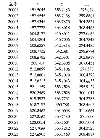
22个控制点地面坐标解算结果如下:
3 近景影像获取
在A、B测站上分别使用主距为24mm和50mm的相机获取控制点影像。不同主距的相机在每个测站分别拍摄3张照片,要保证控制点不被遮挡,最后从中选取成像效果最好的4张影像(24mm左右测站各一张、50mm左右测站各一张),并标注点号。
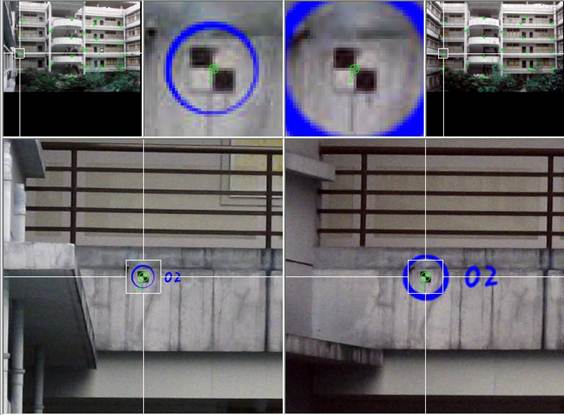
4 LPS刺点点位
运用LPS软件,建立blk并导入左右影像(主距为50mm的),分别在左右影像上刺出22个控制点点位。根据老师要求,将2,8,10,16,20号点设置为控制点,并使用全班成果整理后的坐标成果。
5 光束法平差与精度评定
运用LPS软件进行光束法平差,并生成平差报告:
______________________________________________________________________________________
The Triangulation Report With OrthoBASE
The output image x, y units: pixels
The output angle unit: degrees
The output ground X, Y, Z units: meters
The Input Image Coordinates
image ID = 4
Point ID x y
1 666.103 2764.882
2 670.948 2129.967
3 685.403 1472.574
4 754.414 860.656
5 1652.431 2568.503
6 1600.058 1207.014
7 2312.027 3077.964
8 2346.443 2264.542
9 2334.472 1470.473
10 2361.448 691.079
12 3083.193 2691.257
13 3083.066 1976.987
14 3072.428 1240.419
15 4230.527 2741.493
16 4088.419 2115.427
17 3956.445 1498.102
18 3852.033 888.020
19 4075.943 613.315
20 5203.441 2736.112
21 5214.492 2119.571
22 5144.463 1507.538
23 5139.982 903.989
Affine coefficients from file (pixels) to film (millimeters)
A0 A1 A2 B0 B1 B2
-17.9680 0.006400 0.000000 11.9776 0.000000 -0.006400
image ID = 2
Point ID x y
1 648.624 2765.582
2 650.989 2114.930
3 660.452 1441.411
4 728.563 816.585
5 1965.895 2557.996
6 1910.105 1210.070
7 2767.455 3044.531
8 2792.491 2259.531
9 2774.059 1493.061
10 2791.483 740.514
12 3319.011 2665.417
13 3312.286 1986.582
14 3298.468 1284.901
15 4055.052 2705.029
16 3928.559 2120.490
17 3808.985 1539.018
18 3715.006 962.032
19 3836.444 706.426
20 4883.390 2691.651
21 4890.584 2130.450
22 4754.000 1681.000
23 4825.409 1018.545
Affine coefficients from file (pixels) to film (millimeters)
A0 A1 A2 B0 B1 B2
-17.9680 0.006400 0.000000 11.9776 0.000000 -0.006400
THE OUTPUT OF SELF-CALIBRATING BUNDLE BLOCK ADJUSTMENT
the no. of iteration =1 the standard error = 15.3355
the maximal correction of the object points = 0.37559
the no. of iteration =2 the standard error = 15.3294
the maximal correction of the object points = 0.02823
the no. of iteration =3 the standard error = 15.3224
the maximal correction of the object points = 0.00032
The exterior orientation parameters
image ID Xs Ys Zs PHI OMEGA KAPPA
4 509.6501 301.3448 297.4727 2.1777 4.5969 0.0791
2 497.9149 301.2754 297.2430 14.9560 4.7765 -0.0308
The interior orientation parameters of photos
image ID f(mm) xo(mm) yo(mm)
4 50.0000 0.0000 0.0000
2 50.0000 0.0000 0.0000
The residuals of the control points
Point ID rX rY rZ
2 0.0147 -0.1462 -0.0043
8 -0.0040 -0.0194 0.0035
10 0.0093 0.0866 0.0140
16 -0.0027 -0.0802 -0.0093
21 -0.0691 -0.1206 -0.0013
aX aY aZ
-0.0104 -0.0560 0.0005
mX mY mZ
0.0319 0.1002 0.0080
The residuals of the check points
Point ID rX rY rZ
20 -0.1946 -0.3533 0.0264
aX aY aZ
-0.1946 -0.3533 0.0264
mX mY mZ
0.1946 0.3533 0.0264
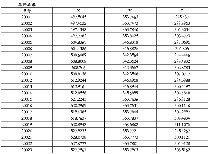
The coordinates of object points
Point ID X Y Z Overlap
2 497.4532 353.7473 299.8953 2
8 508.8008 342.3524 298.6832 2
10 508.8138 342.3548 307.0717 2
16 520.2969 353.7531 300.1146 2
21 527.9857 353.5821 300.1037 2
20 527.7286 353.4188 295.9531 2
1 497.5441 353.5524 295.7110 2
3 497.4312 353.7340 304.2964 2
4 497.7737 353.8339 308.4728 2
5 504.8279 345.7880 297.0654 2
6 504.4323 345.7494 304.8164 2
7 508.6452 342.2944 294.4679 2
9 508.7070 342.3815 302.8826 2
12 512.8962 345.5856 296.4008 2
13 512.9075 345.6695 300.4492 2
14 512.8543 345.6949 304.6957 2
15 521.1896 353.6047 295.9032 2
17 519.4614 353.7789 304.3159 2
18 518.7933 353.8175 308.5273 2
19 520.9328 356.6261 311.1667 2
22 528.4697 356.2666 304.2426 2
23 527.6251 353.5436 308.4655 2
The total object points = 22
The residuals of image points
Point Image Vx Vy
2 4 2.948 1.088
2 2 -2.165 -0.236
Point Image Vx Vy
8 4 0.871 2.574
8 2 -0.215 -1.086
Point Image Vx Vy
10 4 -2.071 -1.164
10 2 2.387 -1.054
Point Image Vx Vy
16 4 -2.122 -6.053
16 2 -3.977 4.893
Point Image Vx Vy
21 4 3.757 -6.125
21 2 0.122 8.256
Point Image Vx Vy
20 4 -0.166 -5.995
20 2 0.247 6.606
Point Image Vx Vy
1 4 0.008 0.435
1 2 -0.011 -0.424
Point Image Vx Vy
3 4 0.010 0.897
3 2 0.015 -0.874
Point Image Vx Vy
4 4 0.005 0.640
4 2 0.023 -0.625
Point Image Vx Vy
5 4 0.033 2.015
5 2 -0.040 -2.041
Point Image Vx Vy
6 4 0.010 1.032
6 2 0.027 -1.044
Point Image Vx Vy
7 4 0.046 2.370
7 2 -0.091 -2.458
Point Image Vx Vy
9 4 0.013 1.199
9 2 0.020 -1.244
Point Image Vx Vy
12 4 -0.015 -0.735
12 2 0.021 0.774
Point Image Vx Vy
13 4 -0.017 -1.048
13 2 0.004 1.103
Point Image Vx Vy
14 4 -0.025 -1.921
14 2 -0.042 2.022
Point Image Vx Vy
15 4 -0.129 -4.955
15 2 0.187 5.324
Point Image Vx Vy
17 4 -0.121 -6.034
17 2 -0.040 6.436
Point Image Vx Vy
18 4 -0.111 -6.471
18 2 -0.182 6.884
Point Image Vx Vy
19 4 -0.161 -8.576
19 2 -0.296 9.153
Point Image Vx Vy
22 4 -2.449 47.170
22 2 4.148 -51.694
Point Image Vx Vy
23 4 -0.218 -9.888
23 2 -0.219 10.878
The image residuals of the control points
The image ID = 4
Point ID Vx Vy
2 2.948 1.088
8 0.871 2.574
10 -2.071 -1.164
16 -2.122 -6.053
21 3.757 -6.125
RMSE of 5 points: mx=2.544, my=4.082
The image ID = 2
Point ID Vx Vy
2 -2.165 -0.236
8 -0.215 -1.086
10 2.387 -1.054
16 -3.977 4.893
21 0.122 8.256
RMSE of 5 points: mx=2.292, my=4.346
The image residuals of the check points
The image ID = 4
Point ID Vx Vy
20 -0.166 -5.995
RMSE of 1 points: mx=0.166, my=5.995
The image ID = 2
Point ID Vx Vy
20 0.247 6.606
RMSE of 1 points: mx=0.247, my=6.606
______________________________________________________________________________________
6 总结
本次近景摄影测量实习历时近9周时间,耗时较长,主要都是在前部分的控制点的量测和解算上耗时较多。三个课时的外业观测时间起初看起来很充裕,但后来才发现非常紧迫,外业观测过程中我们组注意控制了2C值和竖盘指标差不超限,但最后解算出来的坐标与控制点实际地面坐标还是有微小的差距,误差不算很小。在解算坐标的过程中可谓波折多多,首先是没有弄清楚老师指定的坐标系,所有走向了一条更为复杂的道路,在修正过来之后点号与坐标间的对应关系又出了些差错,可见在所有的不论外业还是内业过程,都应将每一阶段的成果整理好,及时检查,一面出现大的错误。
在运用LPS软件进行刺点时,由于本组测站选择的问题,造成有1~2个点被植被遮挡,不是很清楚,可能带来了较大的误差。在刺点和平差阶段我个人只选择了主距为50mm的一组影像来做,因为24mm的影像非常不清晰,误差应该会更大。平差得到的外方位元素还可作为后续的自检校光束平差程序中外方位元素初始值。
通过本次实习,我们更了解了摄影测量作业的一系列过程以及其中很多实践中才能体验到的细节之处,对LPS软件又复习了一遍,使得运用更加自如。最重要的是,我从中弄清了近景摄影测量的原理和方法,还掌握了控制点的一般测量方法,也为后续的程序编写做了准备。