机械工程测试技术
实验指导书
学院: 机械与动力工程学院
专业: 车辆工程
班级: 11010141
学号: 1101014125
姓名: 赵艳峰
实验一 用应变仪测量电阻应变片的灵敏度
一 实验目的
1、掌握在静载荷下使用电阻应变仪测量方法;
2、掌握桥路连接和电阻应变仪工作原理;
3、了解影响测量误差产生的因素。
二、实验仪器及设备
等强度梁 编号;天平秤;砝码;yd-15型动态电阻应变仪;
游标卡尺;千分尺(0~25㎜);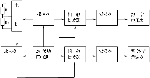 DY-15型直流24伏电源;
三、实验原理
电测法的基本原理是:将电阻应变片粘贴在被测构件的表面,当构件发生变形时,应变片随着构件一起变形(ΔL/L),应变片的电阻值将发生相应的变化,通过电阻应变仪,可测量出应变片中电阻值的变化(ΔR/R),并换算成应变值,或输出与应变成正比的模拟电信号(电压或电流),用记录仪记录下来,也可用计算机按预定的要求进行数据处理,得到所需要的应变或应力值。电阻应变片的灵敏度是构件单位应变所引起应变片电阻值的变化量,用K来表示,
K= =
=
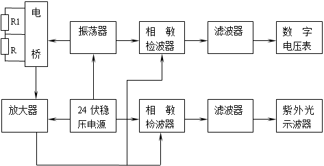
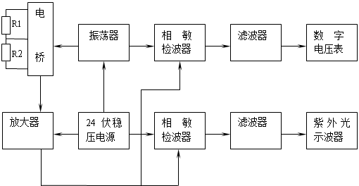 yd-15动态电阻应变仪主要技术参数
1、测量点数:4点 8点
2、测量范围:�10000微应变
3、标定应变:�50,�100,�300,�1000,�3000微应变,标定误差不超过�1%,最小�1微应变
4、灵敏系数:k=2.00
5、灵敏度:0.25mA/με(12Ω及2Ω负载)
0.093 5mA/με(16Ω负载)
0.025mA/με(20Ω负载)
0.01mA/με(50Ω负载)
0.01伏/με(1k负载)
6、电阻应变片:按120Ω设计,100~600Ω可用。
7、线性输出范围:0�30mA(12Ω及2Ω负载)
0�1伏(1k负载)
8、振幅特性误差:低阻输出不超过�1%
电压输出不超过�2%
9、工作频率范围:0~1500hz
10、频率特性误差:低阻输出不超过�6%
电压输出不超过�10
11、电桥电源:10kc,标称电压3伏
12、电阻平衡范围:不小于�0.6Ω(指120Ω应变片)
13、衰减误差:1,3,10,30,100五档,误差不超过�2%
14、电容平衡范围:不小于�2000pf(包括电桥盒内1000pf)
15、稳定性:预热1小时后,零点漂移:不超过�5微应变/2小时,灵敏度变化:不超过�1%/半小时
yd-15动态电阻应变仪工作原理框图
影响测量误差产生的因素
电阻应变片的灵敏系数K的变化,主要是由于温度和湿度的变化引起的。对大多数敏感材料的灵敏系数是随着工作温度的升高和湿度的增大而不断减小的,只有康铜等少数合金的灵敏系数会增大。粘结剂和基底材料传递应变的能力随工作温度的升高也逐渐下降。所以工作温度越高,湿度越大,灵敏系数K值的下降就越快,分散性将会越大。另外,电阻丝受力后其电阻率也会发生变化,从而引起K值的变化。所以在测量时应尽可能保持标定灵敏系数K时的工作环境,从而减小由于工作环境的变化所产生的测量误差。
应变片的绝缘电阻是指已安装的应变片的敏感栅及引线与被测试件之间的电阻值。应变片被安装在试件表面之后,其绝缘电阻的下降将使测量系统的灵敏度降低,使应变仪的指示应变产生误差,另外也使测量系统产生零点漂移。
经计算、实验表明:
工作环境温度越高,湿度越大,灵敏系数下降越快;
电桥非线性对测试结果的影响是很微小的;
(3)测量导线所带来的误差与其长度成正比例;
(4)绝缘电阻越高,稳定性越好,误差越小。
四、实验方法和步骤
1、将电缆焊接到等强度梁的电阻应变片上,用单臂电桥式接入电桥盒,如下图。
工作中只有一个桥臂电阻随着被测量的变化而变化,设改电阻为R1,产生的电阻变化量为ΔR,用万用表检查AB问电阻及BC问阻值,两阻值之差应小子0.5Ω,用电烙铁将连接导线焊接到对应的A,B,C,焊点。为减小干扰,要求屏蔽层(金属网)必须接B点,,将此半桥A,B,C点接入电桥盒对应接线柱上(A, C ,D三接线柱必须短接)。

则输出电压 的值为:
的值为: 
式中,  为输出电压,
 为应变值,ue为供桥电压,和可从分析仪中直接读出,ue在应变仪中读出,K为实验所求。
2、将应变仪预调平衡
(1)准备:正确接桥无误后,打开电源开关;
(2)基零调节:这时衰减开关在“0”位置上,电桥的初始不平衡亦被衰减至零,即放大器无信号输出;
(3)平衡调节:开始调节平衡时,衰减开关从0拨至100处,电表指针偏转,说明电桥初始不平衡,调节电阻平衡电位器R,电容平衡电位器C,使电表指针指到中心位置,然后在衰减至30、10、3、1各档重复上述过程,最后电表指零,表明电桥平衡。
3、将应变仪标定档拨至适当衰减档。
4、在等强度梁上加砝码使应变仪再次平衡。
5、在天平上称出砝码重量,并计算等强度梁的实际应变值。
6、计算电阻应变片的实际灵敏度。
M=PL σ=M/w W=bh2/6 ε=σ/E
式中:M-弯矩 L-P力至应变片中心距离 σ-弯曲应力
b-等强度梁贴应变片处的宽度 h-等强度梁贴应变片处的厚度
ε-实际应变值 W-抗弯截面模量 E-弹性模量E=2.1*106kgf/cm2
五.数据处理与分析


六.实验结果
1、由实验结果可知,悬臂梁因受力而发生形变,并且悬臂的上边要比悬臂的下边发生变形更为明显,因此在此试验中应变片选用正(手拉)应变片较好,试验效果更为明显,相对地减少了误差。
2、在试验中,电压表的示数会有跳动,这会影响实验结果,因此选用一个较为稳定的数或平均值。
提高灵敏度的方法
1.提高桥压。
2.提高应变片的阻值。
3.改用双臂或全桥接法
实验二 测量等强度梁的固有频率和阻尼率
一、实验目的
(1)学会机械系统的固有频率和阻尼率的测定方法
(2)识别悬臂梁的二阶固有频率和阻尼系数
(3)了解并学习东方所振动与噪声测试仪的使用
二、实验仪器
等强度梁 应变仪 动态数据采集仪
三、实验原理
瞬态激励方法给被测系统提供的激励信号是一种瞬态信号,它属于一种宽频带激励,即一次同时给系统提供频带内各个频率成份的能量和使系统产生相应频带内的频率响应。因此,它是一种快速测试方法。同时由于测试设备简单,灵活性大,故常在生产现场使用。目前常用的瞬态激励方法有快速正弦扫描、脉冲锤击和阶跃松弛激励等方法,本实验中采用脉冲锤击产生瞬态信号。
脉冲锤击激励是用脉冲锤对被测系统进行敲击,给系统施加一个脉冲力,使之发生振动。由于锤击力脉冲在一定频率范围内具有平坦的频谱曲线,所以它是一种宽频带的快速激励方法。用脉冲锤敲击试件产生的近似于半正弦的脉冲信号有效频率取决于脉冲持续时间τ,τ越小则频率范围越大。
(1)固有频率,可根据分析仪直接读出固有频率的值。
(2)阻尼比的测定
本实验根据自由衰减法测定阻尼比:即在结构被激起自由振动时,由于存在阻尼,其振幅呈指数衰减波形,可算出阻尼比,下面具体论述。
由振动力学知,二阶系统的特征方程为: ,对应的微分方程为:
 ,其中
,其中 。因为
。因为 ,当
,当 很小时,可以认为
 。
。
减幅系数 ,而
,而 ,
,
则: 。
。
又因为 ,所以
,所以 ,所以
,所以 ,
,
可推出阻尼比公式为:
求解过程:
(1)根据 ~
~ 7个点的幅值,可求出
 ,根据公式
,根据公式 可求出阻尼比。
(2)根据7个点对应的时间 ~
~ ,可用法求出
 ,再根据公式
 ,求出
,求出 。
。 为有阻尼的信号周期,
 为无阻尼信号周期。
(3)从时域图中读出有阻尼固有频率 ,根据
,根据 ,求得无阻尼固有频率
 。
。
四、实验方法
 实验原理图:

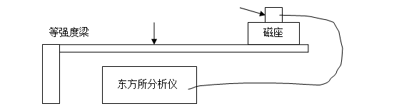
(1)按要求,把各实验仪器连接好接入电脑中,然后在悬臂梁孔处小心放好加速度传感器。
(2)打开计算机,启动计算机上的“振动测试及频谱分析”。
(3)设置适当的采样频率和采样点数以及硬件增益。
(4)点击“采样”后开始敲击。
(5)敲击等强度梁。使用小榔头敲击时注意在敲击后里、榔头要迅速离开梁!避免产生不必要的干扰波形。
(6)数据分析,用东方所分析仪器进行数据分析,使用时域分析可以得到峰值点~,使用频域分析可以直接得到悬臂梁的固有频率 。
。
五、数据处理与分析
将得到的数据输入Matlab中进行处理。首先计算~和~,然后计算阻尼比,最后计算 和。
和。
六、实验结果
(1)等强度梁的固有频率。
从幅值图中可知,等强度梁的固有频率=14.89hz
(图见最后一页,幅值-频率图)
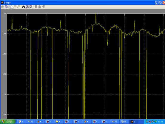
(2)阻尼比。
从幅频中可知幅值 =81.03
  =46.88
故δ= ln
ln ≈0.09,ξ=
 ≈0.014
实验三 振动信号测量与频谱分析
一、实验目的
1.在熟练掌握周期信号幅频特性和相频特性内容的基础上,通过频谱仪对信号的各组成谐波进行直观的、感性的认识和了解。
2.通过对振动信号的测量及频谱分析,了解相关频谱特性和滤波的概念,由频谱图上特征频率寻找该机械设备的振源。
二、实验条件及使用仪器
计算机及MATLAB软件;带USB接口和FFT的4通道数据采集存储示波器TDS2024B;振动测试实验台;激振器;信号发生器,加速度、速度、位移传感器、功率放大器及直流电源等。
三、实验原理
使用傅立叶变换,将采集到的时域信号转换成频域信。
对于二维信号,二维Fourier变换定义为:
二维离散傅立叶变换为:
四、实验内容
1、将TDS2024B示波器与信号发生器连接,观察典型信号的频谱及合成信号的频谱包括:正弦波、方波、三角波、锯齿波等
2、振动信号的测量与数据采集,包括加速度、速度、位移连接振动测试实验台与数字频谱仪,记录4个通道的数据并存盘,在频谱仪上先观察原始时域信号及其傅立叶变换
3、振动信号分析,包括傅立叶分析和功率谱分析等将数据装载到计算机上,利用MATLAB软件进一步分析振动信号的频率成分,计算各个信号的功率谱、被测机械结构的前三阶特征频率,并计算两个信号之间的相关函数及传递率。
五、实验方法与实验步骤
1、将振动与噪声测试仪与加速度传感器连接,安装连接相应的传感器、、直流电源等,开机、设定参数、采集数据,分析处理数据;
2、观察振动信号产生过程,记录通道2产生的数据并存盘分析。
3、根据一组输入输出数据,利用Matlab软件进行时域信号转换成频域信号分析。
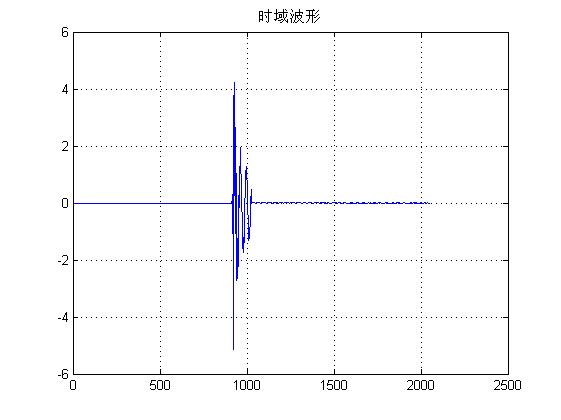
figure(1);
plot(x);%作正弦信号的时域波形
title('时域波形');
grid;
%进行FFT变换并做频谱图
fs=500;
y=fft(x);%进行fft变换
mag=abs(y);%求幅值
f=(0:length(y)-1)'*fs/length(y);%进行对应的频率转换
figure(2);
plot(f,mag);%做频谱图
axis([0,100,0,90]);
xlabel('频率(Hz)');
ylabel('幅值');
title('幅频谱图');
grid;
%求功率谱
sq=abs(y);
power=sq.^2;
figure(3);
plot(f,power);
xlabel('频率(Hz)');
ylabel('功率谱');
title('功率谱');
grid;
六、数据处理与分析
第二篇:工程测试实验报告

目录:
实验一:测试实验
噪声测量及声频分析界面设计
1. 实验目的-----------------------------------------------3
2. 实验原理-----------------------------------------------3
3. 实验内容及设计过程-------------------------------------3
4. M代码及其注释------------------------------------------3
5. Simulink模型-------------------------------------------6
6. C语言代码及注释----------------------------------------7
7. 实验结果----------------------------------------------14
实验二:球杆定位控制系统实验
1. 机械建模分析------------------------------------------16
2. 实验步骤----------------------------------------------16
3. 实验内容及结果----------------------------------------17
总结:
1. 收获与心得体会----------------------------------------31
2. 分工--------------------------------------------------32
实验一 测试部分
1. 实验目的:
a. 掌握用matlab编程,绘制采样数据所得图形,并进行图形分析。
b. 自学matlab编程语言,提升自主学习能力,感受研究生工作。
2. 实验原理:
a. 通过噪声采集卡采集到噪声信号,将噪声信号传送到我们所编好的界面上显示出来,并进行噪声信号频率处理,由幅值—时间坐标系转变为幅值—频率坐标系,得到频率图后通过低通滤波得到有效信号再次转换为幅值—时间信号显示在界面上。
b. 通过上述步骤得到的处理后的信号,我们可以通过计算得到噪声信号的关于频率、幅值、有效值等信息并显示在界面上提供给使用者。
3. 实验内容及设计过程:
a. 通过自学matlab基本操作和调试掌握指令窗运行入门、控制指令窗的指令和操作、数值数组及其运算、matlab控制流、M文件入门、调试器应用示例。
b. 根据噪声测量及声频分析界面特点初步进行数据的可视化和界面设计,依次进行绘图命令、二维曲线绘图的基本操作、句柄图形和界面、属性查询和设置、控制制作以及静态文本框、滑动键、检录框等一系列操作。
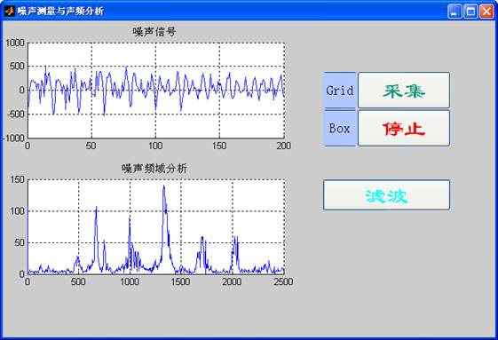
c. 参考实验指导书并根据噪声测量及声频分析界面特点,我们确定噪声信号以及噪声频域分析两个框图大小及位置,设置采集、停止和滤波三个按键。按下采集键时噪声采集卡开始采集数据并将数据传送到介面中显示出来;按下停止键,噪声采集卡停止采集噪声信号,噪声信号框图中的噪声波形固定,噪声频域分析框图显示出进行频域转换后的噪声信号并按照合适的波形大小显示在图框中;按下滤波键,将得到的噪声频域分析图进行滤波处理得到除去高频噪声后的声音信号,并将声音信号重新转换为幅值—时域信号显示在弹出的另一个框图中。
d. 学习simulink动态仿真,掌握simulink模块的数学描述及仿真过程、创建简单模型、进行simulink基本操作、得到simulink子系统创建及封装、构造微分方程求解模型以及多速率离散时间系统。
e. 进行噪声数据采集程序设计,在了解s-function的回调方法及几个主要子函数的基础上编写c语言的s函数---利用s-function模板创建DLL。编写输入输出设置及采集编程将采集到的噪声信号传送到框图中输出。
4. M代码及其注释:
M代码主程序:
clf reset%清楚图形窗口
set(gcf,'menubar','none'); %除去图形窗口菜单栏
set(gcf,'unit','normalized','position',[0.28,0.15,0.70,0.68]); %设置图形界面的位置和大小
set(gcf,'defaultuicontrolhorizontal','left'); %设置用户缺省控件单位位置属性
set(gcf,'defaultuicontrolunits','normalized');%设置用户缺省控件单位属性值
set(gcf,'defaultuicontrolfontsize',14); %设置用户缺省控件字体大小
set(gcf,'defaultuicontrolfontname','隶书');%设置用户缺省控件字体属性
str='噪声测量与声频分析'; %界面标题
set(gcf,'name',str,'numbertitle','off');%书写图形窗名
%%%%%%%%%%%%%%%%%%%%%%%%%%%%%%%%%%%%%%%%%%%%%%
h_axes1=axes('position',[0.05,0.59,0.52,0.32]);%创建“噪声信号”坐标轴
htitle1=title('噪声信号');%坐标轴命名
h_axes2=axes('position',[0.05,0.16,0.52,0.32]);%创建“噪声噪声频域”坐标轴
htitle2=title('噪声频域分析');%坐标轴命名
%%%%%%%%%%%%%%%%%%%%%%%%%%%%%%%%%%%%%%%%%%%%%%
ht1=uicontrol(gcf,'style','toggle','string','Grid',...%制作“栅格”双位按键
'position',[0.65,0.78,0.07,0.12],'fontsize',15,'backgroundcolor',[0.70,0.78,1]);%设置坐标“分格”双位按键属性
set(ht1,'callback','t1_Callback(h_axes1,h_axes2)');%按钮引起回调
ht2=uicontrol(gcf,'style','toggle','string','Box',...%制作双位按键
'position',[0.65,0.66,0.07,0.12],'fontsize',15,'backgroundcolor',[0.70,0.78,1]);%设置双位按键属性
set(ht2,'callback','t2_Callback(h_axes1,h_axes2)');%按钮引起回调
%%%%%%%%%%%%%%%%%%%%%%%%%%%%%%%%%%%%%%%%%%%%%%
h_push1=uicontrol(gcf,'style','push',...
'position',[0.72,0.78,0.19,0.12],'string','采集',...%制作“采集”按钮
'backgroundcolor',[0.75,0.86,0.77],'foregroundcolor',[0.1,0.6,0.5],'fontsize',24);%设置停止“开始”按钮属性
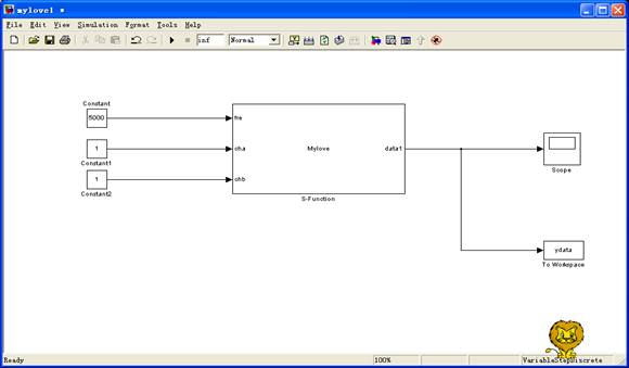
set(h_push1,'callback',[... %让我们前建立的mylove1.mdl文件运行
'set_param(''mylove1'',''SimulationCommand'',''start''),',...
't=timer(''TimerFcn'',''getdata'',''Period'',0.5,''ExecutionMode'',''fixedSpacing'',''TasksToExecute'',inf),',...%设置定时器,运行getdata文件
'pause(2);start(t);',...%暂停2秒并启动定时器
]);%按键引起的回调
h_push2=uicontrol(gcf,'style','push',...
'position',[0.72,0.66,0.19,0.12],'string','停止',...%制作“停止”按钮
'backgroundcolor',[0.72,0.73,0.95],'foregroundcolor',[1,0,0]','fontsize',24);%设置“停止”按钮属性
set(h_push2,'callback','stop(t);set_param(''mylove1'',''simulationcommand'',''stop'');');%mylove.mdl文件停止运行
h_push3=uicontrol(gcf,'style','push',...
'position',[0.65,0.38,0.26,0.10],'string','滤波',...%制作“滤波”按钮
'backgroundcolor',[0.50,0.68,0.88],'foregroundcolor',[0,1,1],'fontsize',24);%设置“滤波”按钮属性
set(h_push3,'callback','push3_Callback()');%按钮引起回调
Getdata.m
set_param('mylove1','SimulationCommand','stop');%mdl文件运行
y1=evalin('base','ydata.signals.values');
axes(h_axes1);
plot(y1(1:500)),htitle1=title('噪声信号');%在第一个波形中绘制波形1
set_param('mylove1','SimulationCommand','start');%mdl文件运行
%以下是频谱分析
N=1024;
P=fft(y1,N);%快速傅里叶变换
Pyy=2*sqrt(P.*conj(P))/N;%求频谱幅值
axes(h_axes2); %在图形窗口中第二坐标中绘图
Fs=5000; %设置频率
f=linspace(0,Fs/2,N/2); %求频谱频率
plot(f,Pyy(1:N/2)),htitle2=title('噪声频域分析');%在第二个波形图中绘制频谱波形
t1_Callback.m %坐标“栅格”子程序
function t1_Callback(h_axes1,h_axes2)')
axes(h_axes1); %调用坐标系1
Grid %坐标系1画“栅格”
axes(h_axes2); %调用坐标系2
Grid %坐标系2画“栅格”
end%子程序结束
t2_Callback.m %坐标轴“分格”子程序
function t2_Callback(h_axes1,h_axes2)')
axes(h_axes1); %调用坐标系1
Box %坐标系1画“分格”
axes(h_axes2); %调用坐标系2
Box %坐标系2画“分格”
end%子程序结束
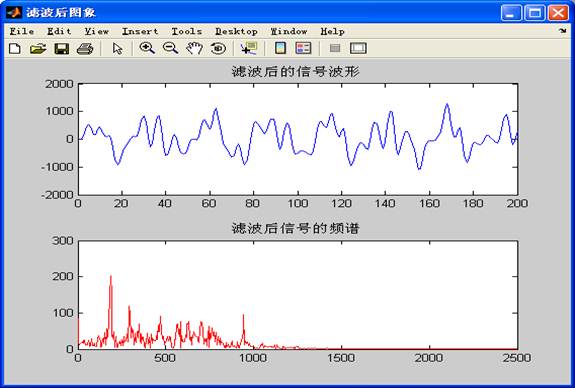
push3_Callback.m
function push3_Callback()
y1=evalin('base','ydata.signals.values');%获取信号
Ft=8000;%设置滤波器参数
Fp=800;%设置滤波器参数
Fs=5000;%设置滤波器参数
wp=2*pi*Fp/Ft;%设置滤波器参数
ws=2*pi*Fs/Ft;%设置滤波器参数
[n11,wn11]=buttord(wp,ws,1,50,'s'); %求低通滤波器的阶数和截止频率
[b11,a11]=butter(n11,wn11,'s'); %求S域的频率响应的参数
[num11,den11]=bilinear(b11,a11,0.5); %利用双线性变换实现频率响应S域到Z域的变换
z11=filter(num11,den11,y1);
N=1024;
P=fft(z11,N);%求滤波后的信号快速傅里叶变换
m11=12*sqrt(P.*conj(P))/N; %求滤波后频谱
f=linspace(0,Fs/2,N/2); %求频谱频率
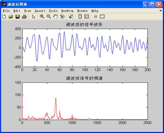
figure(2); %新建图框
str='滤波后图像'; %界面标题
set(gcf,'name',str,'numbertitle','off');%书写图形窗名
subplot(2,1,1);plot(z11);title('滤波后的信号波形');%绘制波形图
subplot(2,1,2);plot(f,m11(1:N/2),'r');title('滤波后信号的频谱');%绘制频谱
end%子程序结束
5. simulink模型
6. c语言代码及注释
mylove.cpp
/*
* sfuntmpl_basic.c: Basic 'C' template for a level 2 S-function.
*
* -------------------------------------------------------------------------
* | See matlabroot/simulink/src/sfuntmpl_doc.c for a more detailed template |
* -------------------------------------------------------------------------
*
* Copyright 1990-2002 The MathWorks, Inc.
* $Revision: 1.27 $
*/
/*
* You must specify the S_FUNCTION_NAME as the name of your S-function
* (i.e. replace sfuntmpl_basic with the name of your S-function).
*/
#define S_FUNCTION_NAME Mylove
#define S_FUNCTION_LEVEL 2
/*
* Need to include simstruc.h for the definition of the SimStruct and
* its associated macro definitions.
*/
#include "simstruc.h"
#include "abc.h" /*添加头文件*/
double buffer[5000]; /*定义全局变量*/
double buffer1[5000];
int pnum;
char ch[8];
/* Error handling
* --------------
*
* You should use the following technique to report errors encountered within
* an S-function:
*
* ssSetErrorStatus(S,"Error encountered due to ...");
* return;
*
* Note that the 2nd argument to ssSetErrorStatus must be persistent memory.
* It cannot be a local variable. For example the following will cause
* unpredictable errors:
*
* mdlOutputs()
* {
* char msg[256]; {ILLEGAL: to fix use "static char msg[256];"}
* sprintf(msg,"Error due to %s", string);
* ssSetErrorStatus(S,msg);
* return;
* }
*
* See matlabroot/simulink/src/sfuntmpl_doc.c for more details.
*/
/*====================*
* S-function methods *
*====================*/
/* Function: mdlInitializeSizes ===============================================
* Abstract:
* The sizes information is used by Simulink to determine the S-function
* block's characteristics (number of inputs, outputs, states, etc.).
*/
static void mdlInitializeSizes(SimStruct *S)
{
/* See sfuntmpl_doc.c for more details on the macros below */
ssSetNumSFcnParams(S, 0); /* Number of expected parameters */
if (ssGetNumSFcnParams(S) != ssGetSFcnParamsCount(S)) {
/* Return if number of expected != number of actual parameters */
return;
}
ssSetNumContStates(S, 0);
ssSetNumDiscStates(S, 0);
if (!ssSetNumInputPorts(S, 3)) return;
ssSetInputPortWidth(S, 0, 1);
ssSetInputPortRequiredContiguous(S, 0, true); /*direct input signal access*/
ssSetInputPortWidth(S, 1, 1);
ssSetInputPortRequiredContiguous(S, 1, true); /*direct input signal access*/
ssSetInputPortWidth(S, 2, 1);
ssSetInputPortRequiredContiguous(S, 2, true); /*direct input signal access*/
/*
* Set direct feedthrough flag (1=yes, 0=no).
* A port has direct feedthrough if the input is used in either
* the mdlOutputs or mdlGetTimeOfNextVarHit functions.
* See matlabroot/simulink/src/sfuntmpl_directfeed.txt.
*/
ssSetInputPortDirectFeedThrough(S, 0, 1);
ssSetInputPortDirectFeedThrough(S, 1, 1);
ssSetInputPortDirectFeedThrough(S, 2, 1);
if (!ssSetNumOutputPorts(S, 1)) return;
ssSetOutputPortWidth(S, 0, 1);
ssSetNumSampleTimes(S, 1);
ssSetNumRWork(S, 0);
ssSetNumIWork(S, 0);
ssSetNumPWork(S, 0);
ssSetNumModes(S, 0);
ssSetNumNonsampledZCs(S, 0);
ssSetOptions(S, 0);
}
/* Function: mdlInitializeSampleTimes =========================================
* Abstract:
* This function is used to specify the sample time(s) for your
* S-function. You must register the same number of sample times as
* specified in ssSetNumSampleTimes.
*/
static void mdlInitializeSampleTimes(SimStruct *S)
{
ssSetSampleTime(S, 0, CONTINUOUS_SAMPLE_TIME);
ssSetOffsetTime(S, 0, 0.0);
}
#define MDL_INITIALIZE_CONDITIONS /* Change to #undef to remove function */
#if defined(MDL_INITIALIZE_CONDITIONS)
/* Function: mdlInitializeConditions ========================================
* Abstract:
* In this function, you should initialize the continuous and discrete
* states for your S-function block. The initial states are placed
* in the state vector, ssGetContStates(S) or ssGetRealDiscStates(S).
* You can also perform any other initialization activities that your
* S-function may require. Note, this routine will be called at the
* start of simulation and if it is present in an enabled subsystem
* configured to reset states, it will be call when the enabled subsystem
* restarts execution to reset the states.
*/
static void mdlInitializeConditions(SimStruct *S)
{
}
#endif /* MDL_INITIALIZE_CONDITIONS */
#define MDL_START /* Change to #undef to remove function */
#if defined(MDL_START)
/* Function: mdlStart =======================================================
* Abstract:
* This function is called once at start of model execution. If you
* have states that should be initialized once, this is the place
* to do it.
*/
static void mdlStart(SimStruct *S) /*添加采集卡初始化及开启采集任务*/
{
if(ADCardInit()!=1)
{
ssSetErrorStatus(S,"Can't find the DAQCard!");
}
DAQ1(0x10,5000,1024*4,buffer); /*开启采集*/
pnum=0; /*初始化buf指针位置*/
}
#endif /* MDL_START */
/* Function: mdlOutputs =======================================================
* Abstract:
* In this function, you compute the outputs of your S-function
* block. Generally outputs are placed in the output vector, ssGetY(S).
*/
static void mdlOutputs(SimStruct *S, int_T tid)
{
int Length=1024*4; /*读取的buffer长度*/
ReadDaq(5,Length,buffer); /*从采集卡读取buffer*/
real_T *y = ssGetOutputPortRealSignal(S,0);/*获取输出指针*/
if (pnum>=Length) pnum=0; /*判断指针是否已满*/
*y=buffer[pnum]; /*输出第pnum个点的值*/
pnum++; /*指针加1*/
}
#define MDL_UPDATE /* Change to #undef to remove function */
#if defined(MDL_UPDATE)
/* Function: mdlUpdate ======================================================
* Abstract:
* This function is called once for every major integration time step.
* Discrete states are typically updated here, but this function is useful
* for performing any tasks that should only take place once per
* integration step.
*/
static void mdlUpdate(SimStruct *S, int_T tid)
{
}
#endif /* MDL_UPDATE */
#define MDL_DERIVATIVES /* Change to #undef to remove function */
#if defined(MDL_DERIVATIVES)
/* Function: mdlDerivatives =================================================
* Abstract:
* In this function, you compute the S-function block's derivatives.
* The derivatives are placed in the derivative vector, ssGetdX(S).
*/
static void mdlDerivatives(SimStruct *S)
{
}
#endif /* MDL_DERIVATIVES */
/* Function: mdlTerminate =====================================================
* Abstract:
* In this function, you should perform any actions that are necessary
* at the termination of a simulation. For example, if memory was
* allocated in mdlStart, this is the place to free it.
*/
static void mdlTerminate(SimStruct *S)
{
ADCardQuit();
} /*退出采集卡*/
/*======================================================*
* See sfuntmpl_doc.c for the optional S-function methods *
*======================================================*/
/*=============================*
* Required S-function trailer *
*=============================*/
#ifdef MATLAB_MEX_FILE /* Is this file being compiled as a MEX-file? */
#include "simulink.c" /* MEX-file interface mechanism */
#else
#include "cg_sfun.h" /* Code generation registration function */
#endif
abc.cpp
#define CHANNEL1 0x01
#define CHANNEL2 0x02
#define CHANNEL3 0x04
#define CHANNEL4 0x08
#define CHANNEL5 0x10
#define CHANNEL6 0x20
#define CHANNEL7 0x40
#define CHANNEL8 0x80
#pragma comment(lib, "DRVIAPI.lib")
extern "C" _declspec(dllimport) int Add(int a,int b);
extern "C" _declspec(dllimport) int ADCardInit(void);
extern "C" _declspec(dllimport) int Daq(unsigned char Channel, //???ù?¨??
unsigned int Frequency,
unsigned short Length,
int Num,
double* wave0 = NULL,
double* wave1 = NULL,
double* wave2 = NULL,
double* wave3 = NULL,
double* wave4 = NULL,
double* wave5 = NULL,
double* wave6 = NULL,
double* wave7 = NULL);
extern "C" __declspec(dllimport)
int ReadDaq(int Channel, int Length, double *buffer);
extern "C" __declspec(dllimport)
int DAQ1(unsigned char Channel, unsigned int Frequency, unsigned short Length, double *wave);
extern "C" __declspec(dllimport)
int DAQ2(unsigned char Channel, unsigned int Frequency, unsigned short Length, double *wave0, double *wave1);
extern "C" __declspec(dllimport)
int DAQ3(unsigned char Channel, unsigned int Frequency, unsigned short Length, double *wave0, double *wave1, double *wave2);
extern "C" __declspec(dllimport)
int DAQ4(unsigned char Channel, unsigned int Frequency, unsigned short Length, double *wave0, double *wave1, double *wave2, double *wave3);
extern "C" __declspec(dllimport)
int DAQ5(unsigned char Channel, unsigned int Frequency, unsigned short Length, double *wave0, double *wave1, double *wave2, double *wave3, double *wave4);
extern "C" __declspec(dllimport)
int DAQ6(unsigned char Channel, unsigned int Frequency, unsigned short Length, double *wave0, double *wave1, double *wave2, double *wave3, double *wave4, double *wave5);
extern "C" __declspec(dllimport)
int DAQ7(unsigned char Channel, unsigned int Frequency, unsigned short Length, double *wave0, double *wave1, double *wave2, double *wave3, double *wave4, double *wave5, double *wave6);
extern "C" __declspec(dllimport)
int DAQ8(unsigned char Channel, unsigned int Frequency, unsigned short Length, double *wave0, double *wave1, double *wave2, double *wave3, double *wave4, double *wave5, double *wave6, double *wave7);
extern "C" __declspec(dllimport) int ADCardQuit(void);
7. 实验结果
A1.采集信号显示并进行频谱分析

A2.进行滤波处理
B1.再次采集另一不同噪声信号
B2.滤波分析
实验二:球杆定位控制系统实验
1. 机械建模分析:
球杆定位系统是一个经典的控制理论数学模型,它具有物理模型简单,概念清晰,便于用控制理论算法进行控制的特点,系统给出一个相对简单的模型。
钢球在滑道加速滚动的力是小球的重力在同滑道平行方向上的分力与摩擦力的合力。钢球滚动的动力学方程,钢球在滑道上滚动加速度:
a=μgcosα- gsinα
其中 为钢球与轨道之间的摩擦系数,而
 为滑道与水平面之间的夹角。
为了简化系统模型,考虑到摩擦系数比较小,摩擦力可以忽略不记,因此,其基本的数学模型转换成如下公式:
..
M x =mgsinα
当<<1时,线性化处理后,得到传递函数如下:
X(s) g
---- = -----
α(s) s^2
其中X(s)为钢球在滑道上的位置。
在实际控制的过程中,滑道的仰角是由电动机的转角输出来实现的。影响电动机转角 和滑道仰角之间的关系的主要因素就是齿轮的减速比和非线性。因此,我们把该模型进一步简化:
(s)=b*(s)
我们可以得到另一个模型:
X(s) c
---- = -----
(s) s^2
期中c是一个包含了b和g的影响的参数。因此球杆系统实际上可以简化为一个二阶系统。
2. 实验步骤:
(1)认真观察球杆定位控制系统,指出系统的各个部分,打开后盖,认知相关的电气控制部分及机械传动部分,并做好记录。
(2)安装好后盖,将电源线,通讯线与电源箱,电脑正常连接。
(3)接通电源,打开测试软件:
1)在matlab下打开QGTEST.MDL进入测试界面
2)点击运行:
3)设置运动位置POS,观察球杆运动情况,
4)切换伺服开关,运动,停止开关,测试硬件响应
5)改变运动速度,加速度及位置,观察运动情况
6)打开各个示波器
7)用手轻拨钢球,让钢球在滑道上缓慢滚动,观察采集到钢球的位置数据
8)停止实时仿真,观察各示波器数据,并保存到相应的文件
3.实验内容及结果:
a. 搭建球杆控制系统及其子系统
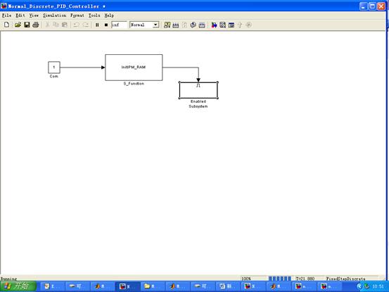
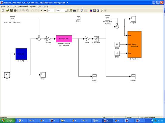
b.球杆模型c代码
Get_AD.cpp
#include "Get_AD.h"
#define WIN32
//#ifndef WIN32
//#error "Only WIN32 version is available"
//#endif
#include "windows.h"
#define S_FUNCTION_LEVEL 2
#define S_FUNCTION_NAME Get_AD
// Need to include simstruc.h for the definition of the SimStruct and
// its associated macro definitions.
#include "simstruc.h"
#include "TML_lib.h"
//#include "TML_lib_compact.h"
#pragma comment(lib, "TML_lib.lib")
#pragma warning( disable: 4761 )
#define IS_PARAM_DOUBLE(pVal) (mxIsNumeric(pVal) && !mxIsLogical(pVal) &&\
!mxIsEmpty(pVal) && !mxIsSparse(pVal) && !mxIsComplex(pVal) && mxIsDouble(pVal))
// Function: mdlInitializeSizes ===============================================
// Abstract:
// The sizes information is used by Simulink to determine the S-function
// block's characteristics (number of inputs, outputs, states, etc.).
static void mdlInitializeSizes(SimStruct *S)
{
// No expected parameters
ssSetNumSFcnParams(S, 0);
// Parameter mismatch will be reported by Simulink
if (ssGetNumSFcnParams(S) != ssGetSFcnParamsCount(S)) {
return;
}
// Specify I/O
//if (!ssSetNumInputPorts(S, 0)) return;
if (!ssSetNumInputPorts(S, 1)) return;
ssSetInputPortWidth(S, 0, DYNAMICALLY_SIZED);
ssSetInputPortDirectFeedThrough(S, 0, 1);
if (!ssSetNumOutputPorts(S,1)) return;
ssSetOutputPortWidth(S, 0, DYNAMICALLY_SIZED);
ssSetNumSampleTimes(S, 1);
// Reserve place for C++ object
ssSetNumPWork(S, 1);
ssSetOptions(S,
SS_OPTION_WORKS_WITH_CODE_REUSE |
SS_OPTION_EXCEPTION_FREE_CODE |
SS_OPTION_USE_TLC_WITH_ACCELERATOR);
}
// Function: mdlInitializeSampleTimes =========================================
// Abstract:
// This function is used to specify the sample time(s) for your
// S-function. You must register the same number of sample times as
// specified in ssSetNumSampleTimes.
static void mdlInitializeSampleTimes(SimStruct *S)
{
ssSetSampleTime(S, 0, CONTINUOUS_SAMPLE_TIME); //INHERITED_SAMPLE_TIME
ssSetOffsetTime(S, 0, 0.0);
ssSetModelReferenceSampleTimeDefaultInheritance(S);
}
// Function: mdlStart =======================================================
// Abstract:
// This function is called once at start of model execution. If you
// have states that should be initialized once, this is the place
// to do it.
#define MDL_START
static void mdlStart(SimStruct *S)
{
// Store new C++ object in the pointers vector
DoubleAdder *da = new DoubleAdder();
// InputRealPtrsType uPtrs = ssGetInputPortRealSignalPtrs(S,0);
ssGetPWork(S)[0] = da;
}
// Function: mdlOutputs =======================================================
// Abstract:
// In this function, you compute the outputs of your S-function
// block. Generally outputs are placed in the output vector, ssGetY(S).
static void mdlOutputs(SimStruct *S, int_T tid)
{
// Retrieve C++ object from the pointers vector
// DoubleAdder *da = static_cast<DoubleAdder *>(ssGetPWork(S)[0]);
// Get data addresses of I/O
InputRealPtrsType u = ssGetInputPortRealSignalPtrs(S,0);
real_T *y = ssGetOutputPortRealSignal(S, 0);
//
// Call AddTo method and return peak value
// y[0] = da->AddTo(*u[0]);
//----------------------------------------
short val_ad;
short AD_No;
WORD adr_AD;
AD_No=*u[0];
adr_AD=0;
if(AD_No==2) adr_AD = 0x23e;
if(AD_No==5) adr_AD = 0x241;
if(adr_AD!=0)
{
TS_GetIntVariable(adr_AD,val_ad);
*y =400.00*((float)(unsigned short)val_ad/65535.00);
}
//-----------------------------------------
}
// Function: mdlTerminate =====================================================
// Abstract:
// In this function, you should perform any actions that are necessary
// at the termination of a simulation. For example, if memory was
// allocated in mdlStart, this is the place to free it.
static void mdlTerminate(SimStruct *S)
{
// Retrieve and destroy C++ object
// DoubleAdder *da = static_cast<DoubleAdder *>(ssGetPWork(S)[0]);
// delete da;
}
// Required S-function trailer
#ifdef MATLAB_MEX_FILE /* Is this file being compiled as a MEX-file? */
#include "simulink.c" /* MEX-file interface mechanism */
#else
#include "cg_sfun.h" /* Code generation registration function */
#endif
InitIPM_RAM.cpp
#include "InitIPM_RAM.h"
#define WIN32
//#ifndef WIN32
//#error "Only WIN32 version is available"
//#endif
#include "windows.h"
#define S_FUNCTION_LEVEL 2
#define S_FUNCTION_NAME InitIPM_RAM
// Need to include simstruc.h for the definition of the SimStruct and
// its associated macro definitions.
#include "simstruc.h"
#include "TML_lib.h"
//#include "TML_lib_compact.h"
#pragma comment(lib, "TML_lib.lib")
#pragma warning( disable: 4761 )
#define IS_PARAM_DOUBLE(pVal) (mxIsNumeric(pVal) && !mxIsLogical(pVal) &&\
!mxIsEmpty(pVal) && !mxIsSparse(pVal) && !mxIsComplex(pVal) && mxIsDouble(pVal))
// Function: mdlInitializeSizes ===============================================
// Abstract:
// The sizes information is used by Simulink to determine the S-function
// block's characteristics (number of inputs, outputs, states, etc.).
static void mdlInitializeSizes(SimStruct *S)
{
// No expected parameters
ssSetNumSFcnParams(S, 0);
// Parameter mismatch will be reported by Simulink
if (ssGetNumSFcnParams(S) != ssGetSFcnParamsCount(S)) {
return;
}
// Specify I/O
//if (!ssSetNumInputPorts(S, 0)) return;
if (!ssSetNumInputPorts(S, 1)) return;
ssSetInputPortWidth(S, 0, DYNAMICALLY_SIZED);
ssSetInputPortDirectFeedThrough(S, 0, 1);
if (!ssSetNumOutputPorts(S,1)) return;
ssSetOutputPortWidth(S, 0, DYNAMICALLY_SIZED);
ssSetNumSampleTimes(S, 1);
// Reserve place for C++ object
ssSetNumPWork(S, 1);
ssSetOptions(S,
SS_OPTION_WORKS_WITH_CODE_REUSE |
SS_OPTION_EXCEPTION_FREE_CODE |
SS_OPTION_USE_TLC_WITH_ACCELERATOR);
}
// Function: mdlInitializeSampleTimes =========================================
// Abstract:
// This function is used to specify the sample time(s) for your
// S-function. You must register the same number of sample times as
// specified in ssSetNumSampleTimes.
static void mdlInitializeSampleTimes(SimStruct *S)
{
ssSetSampleTime(S, 0, INHERITED_SAMPLE_TIME);
ssSetOffsetTime(S, 0, 0.0);
ssSetModelReferenceSampleTimeDefaultInheritance(S);
}
// Function: mdlStart =======================================================
// Abstract:
// This function is called once at start of model execution. If you
// have states that should be initialized once, this is the place
// to do it.
#define MDL_START
static void mdlStart(SimStruct *S)
{
// Store new C++ object in the pointers vector
//DoubleAdder *da = new DoubleAdder();
short rtn;
InputRealPtrsType uPtrs = ssGetInputPortRealSignalPtrs(S,0);
//ssGetPWork(S)[0] = da;
//FILE *pfile;
DWORD nBaud = 115200;
BYTE nHostID = 255;
BYTE nRSType=SERIAL_RS232;
BYTE nPort=1;
WORD start_address;
//pfile=fopen("rtn.txt","wt");
nPort=*uPtrs[0];
rtn=TS_OpenSerialPort(nRSType, nPort, nHostID, nBaud);
//fprintf(pfile,"TS_OpenSerialPort:%d\n",rtn);
rtn=TS_SetupAxis(255,"IPM100.cfg");
//fprintf(pfile,"TS_SetupAxis:%d\n",rtn);
rtn=TS_SelectAxis(255);
//fprintf(pfile,"TS_SelectAxis:%d\n",rtn);
rtn=TS_Reset();
Sleep(100);
//----------------------------------------------
//工作方式选择_20060917
// Download the "Ex29RAM.out" file on the drive
TS_DownloadProgram("mcqg.out", start_address);
// After the file download, execute the downloaded code
TS_GOTO(start_address); // go to the start address of the setup program
// After this, you can start sending on-line commands towards the drive
//----------------------------------------------
rtn=TS_Power(POWER_ON);
//fprintf(pfile,"TS_Power:%d\n",rtn);
//rtn=TS_MoveVelocity(2,0.64,MOVE_IMMEDIATE,FROM_REFERENCE);
rtn=TS_MoveAbsolute(4420, 5, 1, UPDATE_IMMEDIATE, FROM_REFERENCE);
//fprintf(pfile,"TS_MoveVelocity:%d\n",rtn);
//fclose(pfile);
Sleep(100);
}
// Function: mdlOutputs =======================================================
// Abstract:
// In this function, you compute the outputs of your S-function
// block. Generally outputs are placed in the output vector, ssGetY(S).
static void mdlOutputs(SimStruct *S, int_T tid)
{
// Retrieve C++ object from the pointers vector
// DoubleAdder *da = static_cast<DoubleAdder *>(ssGetPWork(S)[0]);
// Get data addresses of I/O
// InputRealPtrsType u = ssGetInputPortRealSignalPtrs(S,0);
real_T *y = ssGetOutputPortRealSignal(S, 0);
// Call AddTo method and return peak value
// y[0] = da->AddTo(*u[0]);
//--------------------------------------------------------------------------------------
/* WORD adr_APOS = 0x228; // address of the APOS TML variable - measured position
long i_APOS = 0; // variable storing the actual position read from the drive
TS_GetLongVariable(adr_APOS, i_APOS); // read the actual position
if (i_APOS<(4420-10)) *y = 1;//*/
//---------------------------------------------------------------------------------------
//Sleep(50);
*y = 1;
}
// Function: mdlTerminate =====================================================
// Abstract:
// In this function, you should perform any actions that are necessary
// at the termination of a simulation. For example, if memory was
// allocated in mdlStart, this is the place to free it.
static void mdlTerminate(SimStruct *S)
{
// Retrieve and destroy C++ object
// TS_MoveAbsolute(0, 3, 0.1, UPDATE_IMMEDIATE,FROM_REFERENCE ); //FROM_MEASURE
// Sleep(200);
// TS_MoveVelocity(0,0.1,MOVE_IMMEDIATE,FROM_REFERENCE);
TS_Power(POWER_OFF);
TS_CloseSerialPort();
// DoubleAdder *da = static_cast<DoubleAdder *>(ssGetPWork(S)[0]);
// delete da;
}
// Required S-function trailer
#ifdef MATLAB_MEX_FILE /* Is this file being compiled as a MEX-file? */
#include "simulink.c" /* MEX-file interface mechanism */
#else
#include "cg_sfun.h" /* Code generation registration function */
#endif
Move_AbS.cpp
#include "Move_Abs.h"
#define WIN32
//#ifndef WIN32
//#error "Only WIN32 version is available"
//#endif
#include "windows.h"
#define S_FUNCTION_LEVEL 2
#define S_FUNCTION_NAME Move_Abs
// Need to include simstruc.h for the definition of the SimStruct and
// its associated macro definitions.
#include "simstruc.h"
#include "TML_lib.h"
//#include "TML_lib_compact.h"
#pragma comment(lib, "TML_lib.lib")
#pragma warning( disable: 4761 )
#define IS_PARAM_DOUBLE(pVal) (mxIsNumeric(pVal) && !mxIsLogical(pVal) &&\
!mxIsEmpty(pVal) && !mxIsSparse(pVal) && !mxIsComplex(pVal) && mxIsDouble(pVal))
// Function: mdlInitializeSizes ===============================================
// Abstract:
// The sizes information is used by Simulink to determine the S-function
// block's characteristics (number of inputs, outputs, states, etc.).
static void mdlInitializeSizes(SimStruct *S)
{
// No expected parameters
int i;
ssSetNumSFcnParams(S, 0);
// Parameter mismatch will be reported by Simulink
if (ssGetNumSFcnParams(S) != ssGetSFcnParamsCount(S)) {
return;
}
// Specify I/O
if (!ssSetNumInputPorts(S, 3)) return;
for(i=0;i<3;i++)
{
ssSetInputPortWidth(S, i, 1);//DYNAMICALLY_SIZED
ssSetInputPortDirectFeedThrough(S, i, 1);
}
if (!ssSetNumOutputPorts(S,0)) return;
// ssSetOutputPortWidth(S, 0, DYNAMICALLY_SIZED);
ssSetNumSampleTimes(S, 1);
// Reserve place for C++ object
ssSetNumPWork(S, 1);
ssSetOptions(S,
SS_OPTION_WORKS_WITH_CODE_REUSE |
SS_OPTION_EXCEPTION_FREE_CODE |
SS_OPTION_USE_TLC_WITH_ACCELERATOR);
}
// Function: mdlInitializeSampleTimes =========================================
// Abstract:
// This function is used to specify the sample time(s) for your
// S-function. You must register the same number of sample times as
// specified in ssSetNumSampleTimes.
static void mdlInitializeSampleTimes(SimStruct *S)
{
ssSetSampleTime(S, 0, CONTINUOUS_SAMPLE_TIME); //INHERITED_SAMPLE_TIME
ssSetOffsetTime(S, 0, 0.0);
ssSetModelReferenceSampleTimeDefaultInheritance(S);
}
// Function: mdlStart =======================================================
// Abstract:
// This function is called once at start of model execution. If you
// have states that should be initialized once, this is the place
// to do it.
#define MDL_START
static void mdlStart(SimStruct *S)
{
// Store new C++ object in the pointers vector
DoubleAdder *da = new DoubleAdder();
InputRealPtrsType uPtrs = ssGetInputPortRealSignalPtrs(S,0);
ssGetPWork(S)[0] = da;
}
// Function: mdlOutputs =======================================================
// Abstract:
// In this function, you compute the outputs of your S-function
// block. Generally outputs are placed in the output vector, ssGetY(S).
static void mdlOutputs(SimStruct *S, int_T tid)
{
// Retrieve C++ object from the pointers vector
// DoubleAdder *da = static_cast<DoubleAdder *>(ssGetPWork(S)[0]);
// Get data addresses of I/O
InputRealPtrsType u = ssGetInputPortRealSignalPtrs(S,0);
real_T *y = ssGetOutputPortRealSignal(S, 0);
//
// Call AddTo method and return peak value
// y[0] = da->AddTo(*u[0]);
//----------------------------------------
short rtn;
FILE *pfile;
pfile=fopen("rtn.txt","wt");
fprintf(pfile,"*u[0]:%ld\n",*u[0]);
fprintf(pfile,"*u[1]:%f\n",*u[1]);
fprintf(pfile,"*u[2]:%f\n",*u[2]);
rtn=TS_MoveAbsolute(*u[0], *u[1] , *u[2], UPDATE_IMMEDIATE, FROM_REFERENCE);
//rtn=TS_MoveAbsolute(2000, 5, 0.01, UPDATE_IMMEDIATE, FROM_REFERENCE);
fprintf(pfile,"TS_MoveAbsolute:%d\n",rtn);
fclose(pfile);
//-----------------------------------------
}
// Function: mdlTerminate =====================================================
// Abstract:
// In this function, you should perform any actions that are necessary
// at the termination of a simulation. For example, if memory was
// allocated in mdlStart, this is the place to free it.
static void mdlTerminate(SimStruct *S)
{
// Retrieve and destroy C++ object
// DoubleAdder *da = static_cast<DoubleAdder *>(ssGetPWork(S)[0]);
// delete da;
}
// Required S-function trailer
#ifdef MATLAB_MEX_FILE /* Is this file being compiled as a MEX-file? */
#include "simulink.c" /* MEX-file interface mechanism */
#else
#include "cg_sfun.h" /* Code generation registration function */
#endif
c. 将小球分别放在横杆的远中近测距得到距离波形
d. 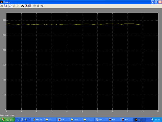

e. 将小球放在衡量任意位置,输入平衡位置,观察横杆定位调节
POS=300
总结:
1. 收获与心得体会:
本次实验我们选到的题目是噪声的测量与声频分析,实验中我们的思想是先通过Simulink调用采集卡采集噪声信号,再将采集噪声传到Matlab工作空间,运行声频分析进行滤波后获取噪声波形及相应的频谱。实验过程中我们遇到许多问题,界面设计是我们经过多方修改,最终定下最后这个方案,采集原始信号并做频谱分析,然后进行滤波并获得频谱,观察两者差异。滤波子程序进过多方设计修改,然后在实验室现场调试,选取合适截止频率,获得理想波形信号。
通过噪声测量及声频分析实验,我们了解并熟悉了Matlab中界面设计的两种基本方法,实验中,我们是通过编写代码实现的,我们还学到了如何利用Simulink搭建模型实现硬件和软件的交互,通过实验我们深刻体会到Matlab是一个功能十分强大的软件,但是她的许多东西对于我们一个初学者是十分困难的,实验实践中需要我们付出时间去熟悉,去用心思考,去实际操作,从基础开始学习,认真走好每一步,才能顺利完成实验。
通过这学期的工程测试综合实验,经过前面噪声信号的采集测试与频谱分析试验,我们还进行了球杆定位控制系统实验,首先搭建曲柄运动的速度、加速度位置控制系统,及小球位置采集系统,并且通过实验对小球的水平位置进行判定,通过该实验对机械机构,电气机构及传感器在工程中的运用有了进一步的认识。最后,我们在黄老师的指导下,对以上几个系统组合,建立PID控制器--控制小球在球杆的某个位置的Simulink控制模型,并通过调节测试实现了小球的位置控制。
通过一系列实验,在黄老师的耐心辅导下,我们进一步了解了MATLAB这一强大的数学工具在工程中的应用,对工程测试知识在工程实际中的应用有了更深一层的认识,同时深刻认识到自己知识的匮乏,衷心感谢黄老师的指导!
2. 分工:
雷翔:matlab界面编写,数据采集滤波程序的编写和注释,simulink仿真模型调试运行
潘绪文:matlab界面编写,波形滤波程序设计,实验报告及总结
闫学文:球杆控制实验的搭建运行调试,simulink仿真模型运行