信息科学与工程学院
FPGA设计及应用实验报告
专业班级 通信工程1202
姓 名 沈佳曼
学 号 20121181086
指导老师 马玲
实验一:彩灯实验报告
一.实验目的
1 通过实验初步了解EDA的基本概念。
2 能理解用VHDL语言实现硬件设计的思路。
3 能熟练掌握EDA开发软件的使用。
二.实验原理
实验中,八个彩灯共阴接地,阳极分别为FPGA的八个I/O相连,I/O输出
变化的电平来控制彩灯的点亮。
三.实验现象

利用light和pin1hz两个模块源程序,成功导入后看的的现象如下:
(1).点阵从左至右按次序渐亮,全亮后逆次序熄灭;
(2).从中间到两边对称的渐亮,全亮后仍由中间向两边逐次渐灭;
(3).奇偶位循环点亮;
(4).从新开始,依次循环。
四.实验中遇到的问题及解决方法
这是第一次实验,前面的内容与之前学习的大同小异,但是在利用两个模块
源程序生成元器件,画完原理图并成功编译后,还需要导入机箱中。
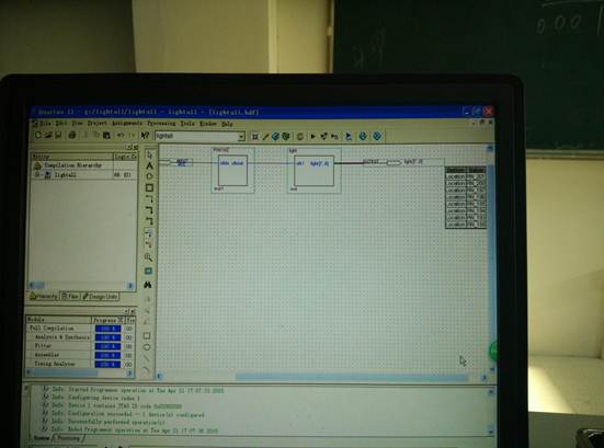
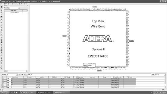
遇到的问题有:1).在对子项目进行管脚绑定时,可供选择的管脚只有两个,clkin和LED,没有LED的八个灯,经检查发现是之前的源程序置顶编译后生成的原理图没有置顶编译,后来解决后成功绑定管脚;(下图为成功绑定后的照片)
2).JTAG模式中,add file时,将后缀为sof的文件加入后,点击start,灯全灭后全亮,并保持这个状态,后来发现是程序中的频率设置出问题,我的第二个模块源程序pin1hz中设置的频率太低导致彩灯闪烁出现问题,在同学建议下我把本来的integer range o to 49中49改为了49999999就很好地观察到了上述现象。
五.改进内容
在完成了课本上的基本内容后,老师进一步要求我们自己看懂主要程序自
己来改变彩灯点亮和熄灭的方式。研究后我把第三种从中间往两边点的方式覆盖到第二种,并且将从中间向两边点改为从中间往两边熄,程序如下:
elsif flag="001"then
light(len downto 4)<=light(len-1 downto 4) &'0';
light(len-4 downto 0)<='0'&light(len-4 downto 1);
if light(1)='0'then
flag:="010";
end if;
elsif flag="010"then
light(len downto 4)<=light(len-1 downto 4) &'1';
light(len-4 downto 0)<='1'&light(len-4 downto 1);
if light(1)='1'then
flag:="011";
end if;
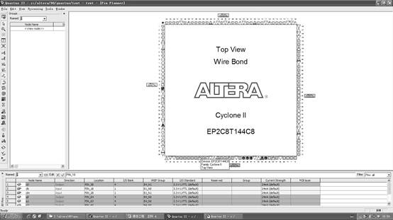
并且将频率49999999换成了4999999,25000000换成了2500000,则频率变成了5M和25M,5M对应10Hz和0.1s,25M对应5HZ和0.2s,将原有的分频放大了10倍,有同学讲其放大了100倍,但灯跑的过快,我觉得还是10倍最直观。(下图为将程序导入机箱时的页面图)

六.实验总结
这次的花样彩灯,让我学会了使用状态机编程,清楚了状态机编程的特点,同时对于点阵的了解也更进了一步。懂得了在程序编译出错的时候要细心并耐心地改正,基本的程序问题应该尽可能的避免,并且要耐心的更正,对于程序必须要弄懂,了解每一次实验的实验原理,不然无法进行相应的程序更改,应付老师的检查并没有多大的意义,更重要的是要在每一次实验中更熟练的操作这些仪器,完善我们的实践能力。另外程序编译成功了不能忘记生成元器件,否则后面画原理图的时候又得重新生成不方便查找,并且每一步都不要忘了先置顶再编译,再生成symbol,不然对后续的实验会有极大的影响。像这样的彩灯实验频率就是其程序很关键的一点,频率影响时间,模式的更改更是其中一项奇妙的设计。最后一点,在实验中一定要细心,不能因为实验现象错误就急躁,问题都是一步一步检查出来的。
七.实验程序
1.“light”
library ieee;
use ieee.std_logic_1164.all;
use ieee.std_logic_unsigned.all;
entity light is
port(clk1: in std_logic;
light: buffer std_logic_vector(7 downto 0));
end light;
architecture behv of light is
constant len : integer:=7;
signal banner: std_logic:='0';
signal clk,clk2: std_logic;
begin
clk<=(clk1 and banner) or (clk2 and not banner);
process(clk1)
begin
if clk1'event and clk1='1' then
clk2<=not clk2;
end if;
end process;
process(clk)
variable flag:bit_vector(2 downto 0):="000";
begin
if clk'event and clk='1' then
if flag="000" then
light<='1'&light(len downto 1);
if light(1)='1'then
flag:="001";
end if;
elsif flag="001" then
light<=light(len-1 downto 0) &'0';
if light(6)='0'then
flag:="010";
end if;
elsif flag="010"then
light(len downto 4)<=light(len-1 downto 4) &'1';
light(len-4 downto 0)<='1'&light(len-4 downto 1);
if light(1)='1'then
flag:="011";
end if;
elsif flag="011" then
light(len downto 4)<='0'&light(len downto 5);
light(len-4 downto 0)<=light(len-5 downto 0) &'0';
if light(2)='0'then
flag:="100";
end if;
elsif flag="100"then
light(len downto 4)<='1'&light(len downto 5);
light(len-4 downto 0)<='1'&light(len-4 downto 1);
if light(1)='1'then
flag:="101";
end if;
elsif flag="101"then
light<="00000000";
flag:="110";
elsif flag="110"then
banner<=not banner;
flag:="000";
end if;
end if;
end process;
end behv;
2.“PIN1hz”
LIBRARY IEEE;
USE IEEE.STD_LOGIC_1164.ALL;
USE IEEE.STD_LOGIC_UNSIGNED.ALL;
ENTITY PIN1HZ IS
PORT(clkin: IN STD_LOGIC;
clkout:OUT STD_LOGIC);
END PIN1HZ;
ARCHITECTURE A OF PIN1HZ IS
BEGIN
PROCESS(clkin)
variable cnttemp: INTEGER RANGE 0 TO 49999999;
BEGIN
IF clkin='1' AND clkin'event THEN
IF cnttemp=49999999 THEN cnttemp:=0;
ELSE
IF cnttemp<25000000 THEN clkout<='1';
ELSE clkout<='0';
END IF;
cnttemp:=cnttemp+1;
END IF;
END IF;
END PROCESS;
END A;
姓名:沈佳曼
班级:通信1202班
学号:20121181086
时间:2015.4.21
第二篇:eda实验报告

EDA实验报告

姓 名 刘欢庭
所在学院 电子信息工程学院
专业班级 2013级通信工程
学 号 013123157
实验一 译码器的设计(2—4译码器)
一、实验目的
1.能了解组合逻辑中译码器电路的设计原理
2.能利用CPLD数字发展实验系统设计一个二对四译码器
3.能自行验证所设计电路的正确性
二、实验内容及要求
设计一个2—4译码器,并下载到实验板进行验证
三、实验器材
1.软件:Altera公司的Quartus Ⅱ软件
2.芯片:Altera公司的EP2C8T144C8
3.开发平台:KH—31001智能型可编程数字开发系统
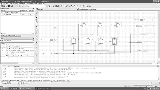
四、实验电路图
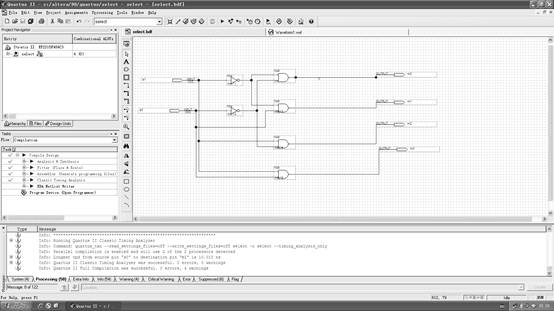
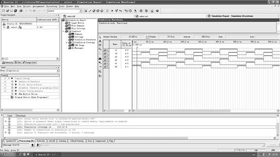
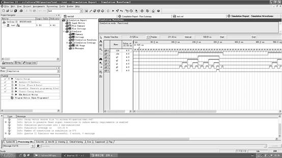
五、功能仿真
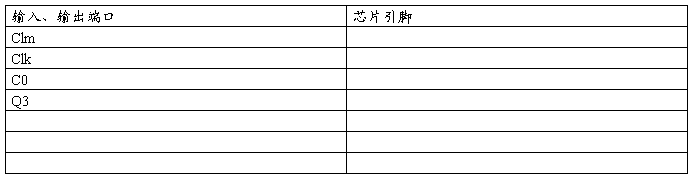
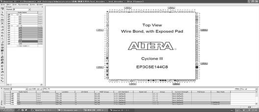
六、引脚分配

实验二 四位二进制同步计数器
一、实验目的
1.能了解四位二进制同步计数器的设计原理及其特性
2.能设计一个四位二进制同步计数器
3.能自行以CPLD数位发展实验系统验证所设计的正确性
二、实验内容及要求
设计一个四位二进制同步计数器电路,并下载到实验板进行验证
三、实验器材
1.软件:Altera公司的Quartus Ⅱ软件
2.芯片:Altera公司的EP2C8T144C8
3.开发平台:KH—31001智能型可编程数字开发系统
四、实验电路图
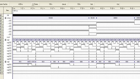
五、功能仿真
六、引脚分配
实验三 BCD对七段显示器译码器
一、实验目的
1.能了解BCD对七段显示器译码器电路的设计原理
2.能利用VHDL语言设计一个BCD对七段显示译码器电路
3.能自行以FPGA/CPLD实验系统验证所设计的正确性
二、实验内容及要求
1.用VHDL语言设计一个BCD对七段显示译码器电路,并下载到实验板进行验证
2.要求:输入信号为四位,并按照BCD码的值进行显示
三、实验器材
1.软件:Altera公司的Quartus Ⅱ软件
2.芯片:Altera公司的EP2C8T144C8
3.开发平台:KH—31001智能型可编程数字开发系统
四、程序代码
library ieee;
use ieee.std_logic_1164.all;
entity bcd_decoder is
port(i:in std_logic_vector(3 downto 0);
y:out std_logic_vector(7 downto 0));
end;
architecture one of bcd_decoder is
begin
process(i)
begin
case is
when"0000"=>y<="11111100";
when"0001"=>y<="01100000";
when"0010"=>y<="11011010";
when"0011"=>y<="11110010";
when"0100"=>y<="01100110";
when"0101"=>y<="10110110";
when"0110"=>y<="10111110";
when"0111"=>y<="11100000";
when"1000"=>y<="11111110";
when"1001"=>y<="11110110";
when"1010"=>y<="11101110";
when"1011"=>y<="00111110";
when"1100"=>y<="10011100";
when"1101"=>y<="01111010";
when"1110"=>y<="10111110";
when"1111"=>y<="10001110";
when others=>y<="11111111";
end case;
end process;
end;
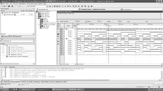
五、功能仿真
六、引脚分配
实验四 交通控制器设计
一、实验目的
1.能了解交通控制器的状态控制及显示设计原理
2.能设计一个交通控制器,并以七段数码显示器显示出倒计时时间
3.能自行以FPGA/CPLD实验系统验证所设计的正确性
二、实验内容
有一条主干道和一条支干道的汇合点形成十字交叉路口,主干道为东西向,支干道为南北向,为确保车辆安全,迅速的通行,在交叉路口的每个入口处设置了红,黄,绿三色信号灯
三、实验要求
(1)主干道绿灯亮时,支干道红灯亮,反之亦然,两者交替允许通行,主干道每次放行35s,支干道每次放行25s每次由绿灯变为红灯的过程中,亮光的黄灯作为过渡,黄灯时间为5s
(2)能实现正常的倒计时显示功能
(3)能实现总体清零功能,计时器由初始状态开始计数,对应状态的指示灯亮
(4)能实现特殊状态的功能显示,进入特殊状态时,东西,南北路口均显示红灯状态
四、实验器材
1.软件:Altera公司的Quartus Ⅱ软件
2.芯片:Altera公司的EP2C8T144C8
3.开发平台:KH—31001智能型可编程数字开发系统
五、实验代码
library ieee;
use ieee.std_logic_1164.all;
use.ieee.std_logic_unsigned.all;
entity jiao_jong is
port(clk,jin:in std_logic;
scan:out std_logic-vector(1 downto 0);
data_out:out std_logic_vector(6 downto 0);
ra,rb,ga,ya,yb:out std_logic);
end;
architecture one of jiao_tong is type states is(st1,st2,st3,st4);
signal clk 1khz,clk1hz:std_logic;
signal one,ten:std_logic_vector(3 downto 0);
signal cnt:std_logic_vector(1 downto 0);
signal data:std_logic_vector(3 downto 0);
singnal data_out1:std_logic_vector(6 downto 0);
signal r1,r2,g1,g2,,y1,y2:std_logic;
begin
process(clk)
variable count:integer range0 to 9999;
begin
if clk'event and clk='1'then
if count=9999 then clk1khz<=not clk1khz;
count=0
else count:=count+1;
end if;
end if;
end process;
process(clk1khz)
variable count:integer range0 to 499;
begin
if clk1khz'event and clk1khz='1'then
if count=499 then clk1khz<=not clk1khz;
count=0
else count:=count+1;
end if;
end if;
end process;
process(clk1hz)
variable stx:states;
variable a:std_logic;
variable qh,ql:std_logic_vector(3 downto 0);
begin
if clk1hz'event and cak1hz='1' then
case stx is
when st1=>if jin'0' then
if a='0'then qh:="0011";ql:="0100";a:='1';
r1<='0';y1<='0';g1<='1';r2<='1';y2<='0';g2<='0'
else if qh=0 and ql=1 then stx:=st2;a:='0';qh:="0000";ql:="0000";
elsif al=0 then ql:="1001";qh:=qh-1;
else ql:=ql-1
end if;
end if;
end if;
when st2=>if jin'0' then
if a='0'then qh:="0000";ql:="0100";a:='1';
r1<='0';y1<='1';g1<='0';r2<='1';y2<='0';g2<='0'
else if qh=0 and ql=1 then stx:=st3;a:='0';qh:="0000";ql:="0000";
elsif ql=0 then ql:="1001";qh:=qh-1;
else ql:=ql-1
end if;
end if;
end if;
when st3=>if jin'0' then
if a='0'then qh:="0010";ql:="0100";a:='1';
r1<='1';y1<='0';g1<='0';r2<='0';y2<='0';g2<='1'
else if qh=0 and ql=1 then stx:=st4;a:='0';qh:="0000";ql:="0000";
elsif ql=0 then ql:="1001";qh:=qh-1;
else ql:=ql-1
end if;
end if;
end if;
when st4=>if jin'0' then
if a='0'then qh:="0000";ql:="0100";a:='1';
r1<='1';y1<='0';g1<='0';r2<='0';y2<='1';g2<='0'
else if qh=0 and ql=1 then stx:=st1;a:='0';qh:="0000";ql:="0000";
elsif ql=0 then ql:="1001";qh:=qh-1;
else ql:=ql-1
end if;
end if;
end if;
end case;
end if;
one<=ql;ten<=qh;
end process;
process(jin,clk1hz,r1,r2,g1,g2,y1,y2,data_out1)
begin
if jin='1' then ra<=r1 or jin;rb<=r2 or jin;ga<=g1 and not jin;
gb<=g2 and not jin;ya<=y1 and not jin;yb<=y2 and not jin;
data_out(0)<=data_out1(0) and clk1hz;
data_out(1)<=data_out1(1) and clk1hz;
data_out(2)<=data_out1(2) and clk1hz;
data_out(3)<=data_out1(3) and clk1hz;
data_out(4)<=data_out1(4) and clk1hz;
data_out(5)<=data_out1(5) and clk1hz;
data_out(6)<=data_out1(6) and clk1hz;
else data_out<=date_out1;ra<=r1;rb<=r2;ga<=g1;gb<=g2;ya<=y1;yb<=y2;
end if;
end process;
process(clk 1khz)
begin
if clk1khz'event and clk1khz='1'then
if cnt="01" then cnt<="00";
else cnt<=cnt+1;
end if;
end if;
end process;
process(cnt,one,ten)
begin
case cnt is
when "00=>data<=one;scan<="01";
when "01=>data<=ten;scan<="10";
when others=>null;
end case;
end process;
process(data)
begin
case data is
when"0000"=>data_out1<="1111110";
when"0001"=>data_out1<="0110000";
when"0010"=>data_out1<="1101101";
when"0100"=>data_out1<="0110011";
when"0101"=>data_out1<="1011011";
when"0110"=>data_out1<="1011111";
when"0111"=>data_out1<="1110000";
when"1000"=>data_out1<="1111111";
when"1011"=>data_out1<="1111011";
when others=>data_out1<="1001111";
end case;
end process;
end;
六、功能仿真