实验一 GPIO 控制 LED
(一) 实验目的:
学习使用ARM开发实验箱STM32的LED部分电路,掌握GPIO的配置编程方法,以及熟悉IAR软件开发环境。
(二) 实验内容:
通过对CPUGPIO的配置,实现对LED灯的控制。
(三) 实验预备知识:
1) IAR软件的编程调试方法。
2) LED部分外围电路的学习。
(四) 实验设备及工具:
硬件:ARM 嵌入式开发平台STM32实验箱, JTAG 仿真器、PC 机。
软件:PC 机、IAR集成开发环境。
(五) 实验分析:
1) 资源分配:
LED灯电路图如下图所示:PC6----PC9分别连到4个LED,因此,控制PC6----PC9各管脚
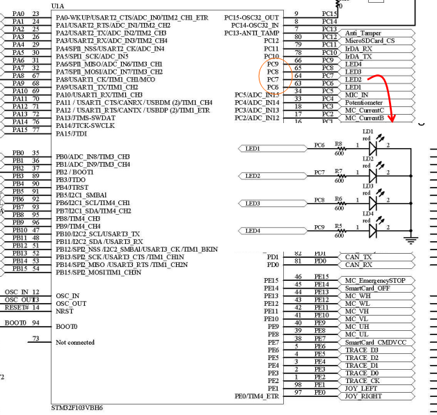
输出电平的高低,就可以控制LED的亮与灭。
2) 软件配置过程:
IAR的EWARM环境下新建工程的过程:打开IAR软件
2.1. 新建空工程
在Project菜单里点 :
:
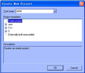
建立空工程,点OK
然后选择保存工程的路径(专门建立文件夹),并输入工程名称,比如Project1,然后点一下保存。
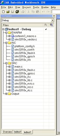
在此路径下拷贝一些工程要用的文件(在ledtest文件夹下):
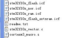
图中的文件是工程必须的文件,从其他现成的EWARM工程中拷贝过来。
STM32f10x_vector.c文件是向量表的C语言文件。
这里以GPIO案例的源文件为例。SRC文件夹里是GPIO案例的源文件,LIB是用到库源文件,包括对应头文件。
2.2. 设置工程属性
首先对工程进行设置。在EWARM里,有两个默认的配置,一个是DEBUG,一个是RELEASE,前者用于调试,后者用于发行。二者的设置不同,并需要分别设置。
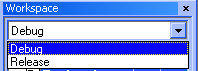
可以选中其中一个进行设置。

在工程上点右键,菜单里点Options。弹出对话框:
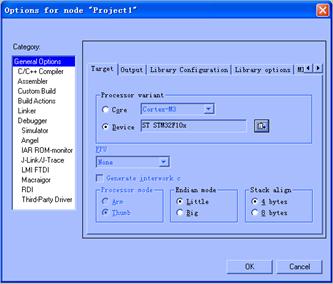
首先如图选择Device,然后点 ,在列表里选择ST,再选STM32F10X
如果不做特别说明,DEBUG和RELEASE的设置相同。
下面是要用的一些内容,填到相应位置
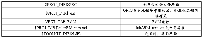
选择C/C++ Compiler,选Preprocessor选项卡,如下图设置
这里的路径和工程在硬盘上的文件夹结构有关,总之是使编译器能够搜索到相应的文件。
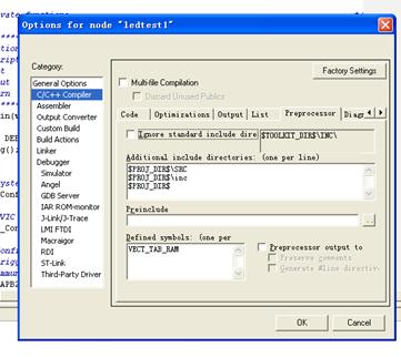
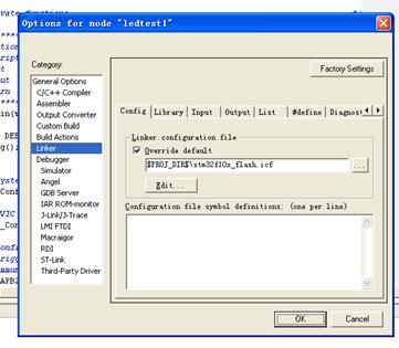
选择Linker里的Config选项卡,如下图设置。这是DEBUG配置的。
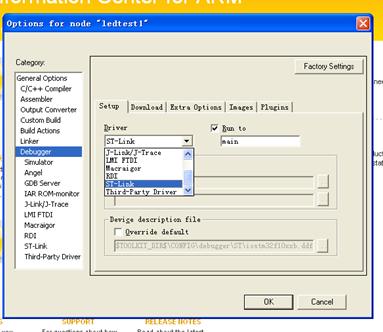
选择Debugger选项,在setup选项卡中的driver下选择ST-link
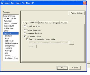
在download选项里,选中user flash loader,下载到目标板的flash中
2.3. 为工程添加需要的文件
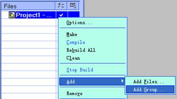
在工程上点右键菜单,点Add,Add Group,添加组,一般和硬盘上文件夹结构相同。添加组需要手动输入组的名称。
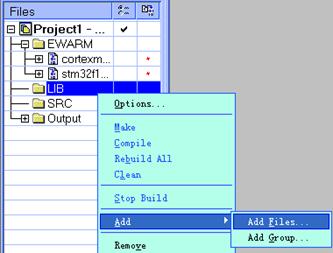
在新建好的组上点右键,点Add,点Add Files可以为该组添加文件,在打开对话框中选择工程目录下的文件即可,可以多选。这里也可以为组建立子组,和文件夹类似。
一般按硬盘目录建立组,再把目录下的文件加入对应的组里。
最后加好的文件如下:其中main文件,也到ledtest中拷贝至当前工程文件夹下。
(3) 实验步骤:
1. 连接电源,连接st-link到实验箱的jtag口,并打开电源。
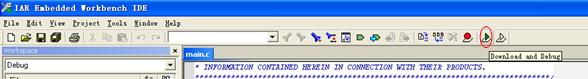
2. 打开MAIN.C 中的内容,点击debugger and download:
3. 用IAR 编译程序,然后用仿真器下载到开发板。
4. 运行程序,观察现象。
5. 进入DEBUG调试环境,单步调试,深入分析程序实现的方法。
(七) 作业:
试着实现LED灯不同点亮顺序,分析实验程序,完成实验报告
第二篇:STM32实验main
第一次实验main.c
#include "stm32f10x_lib.h"
/* Private typedef
-----------------------------------------------------------*/ /* Private define
------------------------------------------------------------*/ //#define ADC1_DR_Address ((u32)0x4001244C)
//#define DATAPORT (u16)(GPIO_Pin_14 | GPIO_Pin_13 | GPIO_Pin_12 | GPIO_Pin_11 | GPIO_Pin_10 | GPIO_Pin_9 | GPIO_Pin_8)
//#define DATAPORT (u8)(GPIO_Pin_11 | GPIO_Pin_10 | GPIO_Pin_9 | GPIO_Pin_8)
/* Private macro
-------------------------------------------------------------*/ /* Private variables
---------------------------------------------------------*/
ErrorStatus HSEStartUpStatus;
/* Private function prototypes
-----------------------------------------------*/
void RCC_Configuration(void);
void GPIO_Configuration(void);
//void NVIC_Configuration(void);
void SysTick_Config(void);
//void LcdShow_Init(void);
/* Private functions
---------------------------------------------------------*/
/*延时子程序,可改变LED亮灭的速度和数码管扫描速度*/
void delay(void);
void delay()
{
int i,j=0;
for (i=0; i<0xFFFFF; i++) j++; //555ms
}
char display[4]={0,0};
/*******************************************************************************
* Function Name : main
* Description : Main program
* Input : None
* Output : None
* Return : None
*******************************************************************************/
int main(void)
{
#ifdef DEBUG
debug();
#endif
/* System clocks configuration
---------------------------------------------*/
RCC_Configuration();
/* GPIO configuration
------------------------------------------------------*/
GPIO_Configuration();
/* Configure the systick */
SysTick_Config();
while(1){
/*四个LED分别接GPIO_Pin_7、GPIO_Pin_6、GPIO_Pin_5、GPIO_Pin_4*/ GPIO_SetBits(GPIOC, GPIO_Pin_7);
GPIO_SetBits(GPIOC, GPIO_Pin_5);
GPIO_ResetBits(GPIOC, GPIO_Pin_6);
GPIO_ResetBits (GPIOC, GPIO_Pin_4);
delay();
GPIO_ResetBits(GPIOC, GPIO_Pin_7);
GPIO_ResetBits (GPIOC, GPIO_Pin_5);
GPIO_SetBits(GPIOC, GPIO_Pin_6);
GPIO_SetBits(GPIOC, GPIO_Pin_4);
delay();
//delay();
//delay();
//GPIO_ResetBits(GPIOC, GPIO_Pin_8);
//GPIO_ResetBits(GPIOC, GPIO_Pin_9);
//GPIO_ResetBits(GPIOC, GPIO_Pin_10);
//GPIO_ResetBits(GPIOC, GPIO_Pin_11);
//GPIO_Write(GPIOE, 0x4900);
//delay();
//delay();
//delay();
}
//#endif
}
/*******************************************************************************
* Function Name : RCC_Configuration
* Description : Configures the different system clocks. * Input : None
* Output : None
* Return : None
*******************************************************************************/
void RCC_Configuration(void)
{
/* RCC system reset(for debug purpose) */
RCC_DeInit();
/* Enable HSE */
RCC_HSEConfig(RCC_HSE_ON);
/* Wait till HSE is ready */
HSEStartUpStatus = RCC_WaitForHSEStartUp();
if(HSEStartUpStatus == SUCCESS)
{
/* Enable Prefetch Buffer */
FLASH_PrefetchBufferCmd(FLASH_PrefetchBuffer_Enable);
/* Flash 2 wait state */
FLASH_SetLatency(FLASH_Latency_2);
/* HCLK = SYSCLK */
RCC_HCLKConfig(RCC_SYSCLK_Div1);
/* PCLK2 = HCLK */
RCC_PCLK2Config(RCC_HCLK_Div1);
/* PCLK1 = HCLK/2 */
RCC_PCLK1Config(RCC_HCLK_Div2);
/* PLLCLK = 4MHz * 14 = 56 MHz */
RCC_PLLConfig(RCC_PLLSource_HSE_Div1, RCC_PLLMul_14);
/* Enable PLL */
RCC_PLLCmd(ENABLE);
/* Wait till PLL is ready */
while(RCC_GetFlagStatus(RCC_FLAG_PLLRDY) == RESET)
{
}
/* Select PLL as system clock source */
RCC_SYSCLKConfig(RCC_SYSCLKSource_PLLCLK);
/* Wait till PLL is used as system clock source */
while(RCC_GetSYSCLKSource() != 0x08)
{
}
}
RCC_APB2PeriphClockCmd(RCC_APB2Periph_GPIOC, ENABLE);
RCC_APB2PeriphClockCmd(RCC_APB2Periph_GPIOE, ENABLE);
}
/*******************************************************************************
* Function Name : GPIO_Configuration
* Description : Configures the different GPIO ports.
* Input : None
* Output : None
* Return : None
*******************************************************************************/
void GPIO_Configuration(void)
{
GPIO_InitTypeDef GPIO_InitStructure;
GPIO_InitStructure.GPIO_Pin =
GPIO_Pin_7|GPIO_Pin_8|GPIO_Pin_9|GPIO_Pin_10|GPIO_Pin_11;
GPIO_InitStructure.GPIO_Mode =GPIO_Mode_Out_PP;//GPIO_Mode_AF_OD;// GPIO_InitStructure.GPIO_Speed = GPIO_Speed_10MHz;
GPIO_Init(GPIOC, &GPIO_InitStructure);
GPIO_InitStructure.GPIO_Pin = GPIO_Pin_All;
GPIO_InitStructure.GPIO_Mode = GPIO_Mode_Out_PP;
GPIO_InitStructure.GPIO_Speed = GPIO_Speed_10MHz;
GPIO_Init(GPIOE, &GPIO_InitStructure);
}
void SysTick_Config(void)
{
/* Configure HCLK clock as SysTick clock source */
SysTick_CLKSourceConfig(SysTick_CLKSource_HCLK);
/* SysTick interrupt each 100 Hz with HCLK equal to 72MHz */ SysTick_SetReload(720000);
/* Enable the SysTick Interrupt */
SysTick_ITConfig(ENABLE);
/* Enable the SysTick Counter */
SysTick_CounterCmd(SysTick_Counter_Enable);
}
#ifdef DEBUG
/*******************************************************************************
* Function Name : assert_failed
* Description : Reports the name of the source file and the source line number
* where the assert_param error has occurred. * Input : - file: pointer to the source file name
* - line: assert_param error line source number * Output : None
* Return : None
*******************************************************************************/
void assert_failed(u8* file, u32 line)
{
/* User can add his own implementation to report the file name and line number,
ex: printf("Wrong parameters value: file %s on line %d\r\n", file, line) */
/* Infinite loop */
while (1)
{
}
}
#endif
/******************* (C) COPYRIGHT 2007 STMicroelectronics *****END OF FILE****/
第二次实验main.c
#include "stm32f10x_lib.h"
/* Private typedef
-----------------------------------------------------------*/ /* Private define
------------------------------------------------------------*/ //#define ADC1_DR_Address ((u32)0x4001244C)
//#define DATAPORT (u16)(GPIO_Pin_14 | GPIO_Pin_13 | GPIO_Pin_12 | GPIO_Pin_11 | GPIO_Pin_10 | GPIO_Pin_9 | GPIO_Pin_8)
//#define DATAPORT (u8)(GPIO_Pin_11 | GPIO_Pin_10 | GPIO_Pin_9 | GPIO_Pin_8)
/* Private macro
-------------------------------------------------------------*/ /* Private variables
---------------------------------------------------------*/
ErrorStatus HSEStartUpStatus;
/* Private function prototypes
-----------------------------------------------*/
void RCC_Configuration(void);
void GPIO_Configuration(void);
//void NVIC_Configuration(void);
void SysTick_Config(void);
//void LcdShow_Init(void);
/* Private functions
---------------------------------------------------------*/
void delay(void);
void delay()
{
int i,j=0;
for (i=0; i<10000; i++) j++; //555ms
}
char display[4]={0,0};
u8 const LED[]={0x40,0x79,0x24,0x30,0x19,0x12,0x02,0x78,0x00,0x10};
/*******************************************************************************
* Function Name : main
* Description : Main program
* Input : None
* Output : None
* Return : None
*******************************************************************************/
int main(void)
{
#ifdef DEBUG
debug();
#endif
/* System clocks configuration
---------------------------------------------*/
RCC_Configuration();
/* GPIO configuration
------------------------------------------------------*/
GPIO_Configuration();
/* Configure the systick */
SysTick_Config();
while(1){
GPIO_Write(GPIOE, 0x7900); //显示
GPIO_ResetBits(GPIOC, GPIO_Pin_8);
GPIO_SetBits(GPIOC, GPIO_Pin_9);
GPIO_SetBits(GPIOC, GPIO_Pin_10);
GPIO_SetBits(GPIOC, GPIO_Pin_11);
delay();
GPIO_Write(GPIOE, 0x2400); //显示
GPIO_SetBits(GPIOC, GPIO_Pin_8);
GPIO_ResetBits(GPIOC, GPIO_Pin_9);
GPIO_SetBits(GPIOC, GPIO_Pin_10);
GPIO_SetBits(GPIOC, GPIO_Pin_11);
delay();
GPIO_Write(GPIOE, 0x3000);//显示
GPIO_SetBits(GPIOC, GPIO_Pin_8);
GPIO_SetBits(GPIOC, GPIO_Pin_9);
GPIO_ResetBits(GPIOC, GPIO_Pin_10);
GPIO_SetBits(GPIOC, GPIO_Pin_11);
delay();
GPIO_Write(GPIOE, 0x1900);//显示
GPIO_SetBits(GPIOC, GPIO_Pin_8);
GPIO_SetBits(GPIOC, GPIO_Pin_9);
GPIO_SetBits(GPIOC, GPIO_Pin_10);
GPIO_ResetBits(GPIOC, GPIO_Pin_11);
delay();
//GPIO_SetBits(GPIOC, GPIO_Pin_7);
//delay();
//GPIO_ResetBits(GPIOC, GPIO_Pin_7);
//delay();
//delay();
//delay();
//GPIO_ResetBits(GPIOC, GPIO_Pin_8);
//GPIO_ResetBits(GPIOC, GPIO_Pin_9);
//GPIO_ResetBits(GPIOC, GPIO_Pin_10);
//GPIO_ResetBits(GPIOC, GPIO_Pin_11);
//GPIO_Write(GPIOE, 0x4900);
//delay();
//delay();
//delay();
}
//#endif
}
/*******************************************************************************
* Function Name : RCC_Configuration
* Description : Configures the different system clocks. * Input : None
* Output : None
* Return : None
*******************************************************************************/
void RCC_Configuration(void)
{
/* RCC system reset(for debug purpose) */
RCC_DeInit();
/* Enable HSE */
RCC_HSEConfig(RCC_HSE_ON);
/* Wait till HSE is ready */
HSEStartUpStatus = RCC_WaitForHSEStartUp();
if(HSEStartUpStatus == SUCCESS)
{
/* Enable Prefetch Buffer */
FLASH_PrefetchBufferCmd(FLASH_PrefetchBuffer_Enable);
/* Flash 2 wait state */
FLASH_SetLatency(FLASH_Latency_2);
/* HCLK = SYSCLK */
RCC_HCLKConfig(RCC_SYSCLK_Div1);
/* PCLK2 = HCLK */
RCC_PCLK2Config(RCC_HCLK_Div1);
/* PCLK1 = HCLK/2 */
RCC_PCLK1Config(RCC_HCLK_Div2);
/* PLLCLK = 4MHz * 14 = 56 MHz */
/* PLLCLK = 8MHz * 9 = 72MHz 修改值
/*RCC_PLLConfig(RCC_PLLSource_HSE_Div1, RCC_PLLMul_14);*/
RCC_PLLConfig(RCC_PLLSource_HSE_Div1, RCC_PLLMul_9); //修改了
/* Enable PLL */
RCC_PLLCmd(ENABLE);
/* Wait till PLL is ready */
while(RCC_GetFlagStatus(RCC_FLAG_PLLRDY) == RESET)
{
}
/* Select PLL as system clock source */
RCC_SYSCLKConfig(RCC_SYSCLKSource_PLLCLK);
/* Wait till PLL is used as system clock source */
while(RCC_GetSYSCLKSource() != 0x08)
{
}
}
RCC_APB2PeriphClockCmd(RCC_APB2Periph_GPIOC, ENABLE);
RCC_APB2PeriphClockCmd(RCC_APB2Periph_GPIOE, ENABLE);
}
/*******************************************************************************
* Function Name : GPIO_Configuration
* Description : Configures the different GPIO ports.
* Input : None
* Output : None
* Return : None
*******************************************************************************/
void GPIO_Configuration(void)
{
GPIO_InitTypeDef GPIO_InitStructure;
GPIO_InitStructure.GPIO_Pin =
GPIO_Pin_7|GPIO_Pin_8|GPIO_Pin_9|GPIO_Pin_10|GPIO_Pin_11;
GPIO_InitStructure.GPIO_Mode =GPIO_Mode_Out_PP;//GPIO_Mode_AF_OD;// GPIO_InitStructure.GPIO_Speed = GPIO_Speed_10MHz;
GPIO_Init(GPIOC, &GPIO_InitStructure);
GPIO_InitStructure.GPIO_Pin = GPIO_Pin_All;
GPIO_InitStructure.GPIO_Mode = GPIO_Mode_Out_PP;
GPIO_InitStructure.GPIO_Speed = GPIO_Speed_10MHz;
GPIO_Init(GPIOE, &GPIO_InitStructure);
}
void SysTick_Config(void)
{
/* Configure HCLK clock as SysTick clock source */
SysTick_CLKSourceConfig(SysTick_CLKSource_HCLK);
/* SysTick interrupt each 100 Hz with HCLK equal to 72MHz */ SysTick_SetReload(720000);
/* Enable the SysTick Interrupt */
SysTick_ITConfig(ENABLE);
/* Enable the SysTick Counter */
SysTick_CounterCmd(SysTick_Counter_Enable);
}
#ifdef DEBUG
/*******************************************************************************
* Function Name : assert_failed
* Description : Reports the name of the source file and the source line number
* where the assert_param error has occurred. * Input : - file: pointer to the source file name
* - line: assert_param error line source number * Output : None
* Return : None
*******************************************************************************/
void assert_failed(u8* file, u32 line)
{
/* User can add his own implementation to report the file name and line number,
ex: printf("Wrong parameters value: file %s on line %d\r\n", file, line) */
/* Infinite loop */
while (1)
{
}
}
#endif
/******************* (C) COPYRIGHT 2007 STMicroelectronics *****END OF FILE****/
第三次实验main.c
#include "stm32f10x_lib.h"
/* Local includes
------------------------------------------------------------*/ /* Private typedef
-----------------------------------------------------------*/ u8 LED_MODE = 0;
/* Private functions
---------------------------------------------------------*/ void RCC_Configuration(void);
void GPIO_Configuration(void);
void NVIC_Configuration(void);
void EXTI_Configuration(void);
void delay(void);
void delay()
{
u32 i;
for (i=0; i<1000000; i++);
}
/*******************************************************************************
* Function Name : main
* Description : Main program
* Input : None
* Output : None
* Return : None
*******************************************************************************/
int main(void)
{
#ifdef DEBUG
debug();
#endif
/* System Clocks Configuration */
RCC_Configuration();
NVIC_Configuration();
EXTI_Configuration();
GPIO_Configuration();
while (1)
{
if(LED_MODE==0)
{
GPIO_ResetBits(GPIOC, GPIO_Pin_4);
GPIO_ResetBits(GPIOC, GPIO_Pin_5);
GPIO_ResetBits(GPIOC, GPIO_Pin_6);
GPIO_ResetBits(GPIOC, GPIO_Pin_7);
delay();
GPIO_WriteBit(GPIOC, GPIO_Pin_4, (BitAction)(1 -
GPIO_ReadOutputDataBit(GPIOC, GPIO_Pin_4)));//这句话的意思是,如果原来是亮就让它灭,如果原来不亮就让它亮
delay();
GPIO_WriteBit(GPIOC, GPIO_Pin_5, (BitAction)(1 -
GPIO_ReadOutputDataBit(GPIOC, GPIO_Pin_5)));
delay();
GPIO_WriteBit(GPIOC, GPIO_Pin_6, (BitAction)(1 -
GPIO_ReadOutputDataBit(GPIOC, GPIO_Pin_6)));
delay();
GPIO_WriteBit(GPIOC, GPIO_Pin_7, (BitAction)(1 -
GPIO_ReadOutputDataBit(GPIOC, GPIO_Pin_7)));
delay();
}
else if(LED_MODE==1)
{
GPIO_ResetBits(GPIOC, GPIO_Pin_4);
GPIO_ResetBits(GPIOC, GPIO_Pin_6);
GPIO_WriteBit(GPIOC, GPIO_Pin_5, (BitAction)(1 -
GPIO_ReadOutputDataBit(GPIOC, GPIO_Pin_5)));
delay();
GPIO_WriteBit(GPIOC, GPIO_Pin_7, (BitAction)(1 -
GPIO_ReadOutputDataBit(GPIOC, GPIO_Pin_7)));
delay();
}
else if(LED_MODE==2)
{
GPIO_ResetBits(GPIOC, GPIO_Pin_5);
GPIO_ResetBits(GPIOC, GPIO_Pin_7);
GPIO_WriteBit(GPIOC, GPIO_Pin_4, (BitAction)(1 -
GPIO_ReadOutputDataBit(GPIOC, GPIO_Pin_4)));
delay();
GPIO_WriteBit(GPIOC, GPIO_Pin_6, (BitAction)(1 -
GPIO_ReadOutputDataBit(GPIOC, GPIO_Pin_6)));
delay();
}
}
}
/*******************************************************************************
* Function Name : RCC_Configuration
* Description : Configures the different system clocks. * Input : None
* Output : None
* Return : None
*******************************************************************************/
void RCC_Configuration(void)
{
ErrorStatus HSEStartUpStatus;
RCC_DeInit();
/* Enable HSE */
RCC_HSEConfig(RCC_HSE_ON);
/* Wait till HSE is ready */
HSEStartUpStatus = RCC_WaitForHSEStartUp();
if(HSEStartUpStatus == SUCCESS)
{
/* Enable Prefetch Buffer */
FLASH_PrefetchBufferCmd(FLASH_PrefetchBuffer_Enable);
/* Flash 2 wait state */
FLASH_SetLatency(FLASH_Latency_2);
/* HCLK = SYSCLK */
RCC_HCLKConfig(RCC_SYSCLK_Div1);
/* PCLK2 = HCLK */
RCC_PCLK2Config(RCC_HCLK_Div1);
/* PCLK1 = HCLK/2 */
RCC_PCLK1Config(RCC_HCLK_Div2);
/* ADCCLK = PCLK2/4 */
RCC_ADCCLKConfig(RCC_PCLK2_Div4);
/* PLLCLK = 8MHz * 9 = 72 MHz */
RCC_PLLConfig(RCC_PLLSource_HSE_Div1, RCC_PLLMul_9); //时钟为M
/* Enable PLL */
RCC_PLLCmd(ENABLE);
/* Wait till PLL is ready */
while(RCC_GetFlagStatus(RCC_FLAG_PLLRDY) == RESET)
{
}
/* Select PLL as system clock source */
RCC_SYSCLKConfig(RCC_SYSCLKSource_PLLCLK);
/* Wait till PLL is used as system clock source */
while(RCC_GetSYSCLKSource() != 0x08)
{
}
}
/*HSL GPIOD, GPIOC and AFIO clock enable */
RCC_APB2PeriphClockCmd(RCC_APB2Periph_GPIOD | RCC_APB2Periph_GPIOC | RCC_APB2Periph_AFIO, ENABLE);// 使用中断时要开启AFIO时钟
}
/*******************************************************************************
* Function Name : NVIC_Configuration
* Description : Configures the NVIC and Vector Table base address. * Input : None
* Output : None
* Return : None
*******************************************************************************/
void NVIC_Configuration(void)
{
NVIC_InitTypeDef NVIC_InitStructure;
#ifdef VECT_TAB_RAM
/* Set the Vector Table base location at 0x20000000 */
NVIC_SetVectorTable(NVIC_VectTab_RAM, 0x0);
#else /* VECT_TAB_FLASH */
/* Set the Vector Table base location at 0x08000000 */
NVIC_SetVectorTable(NVIC_VectTab_FLASH, 0x0);
#endif
NVIC_PriorityGroupConfig(NVIC_PriorityGroup_1); //1、先指定优先级组
// enable the EXTI3 Interrupt instead //2、指定要使用的中断及使其中断使能
NVIC_InitStructure.NVIC_IRQChannel = EXTI3_IRQChannel;
NVIC_InitStructure.NVIC_IRQChannelPreemptionPriority = 0;
NVIC_InitStructure.NVIC_IRQChannelSubPriority = 0;
NVIC_InitStructure.NVIC_IRQChannelCmd = ENABLE;
NVIC_Init(&NVIC_InitStructure);
// enable the EXTI4 Interrupt instead //2、指定要使用的中断及使其中断使能
NVIC_InitStructure.NVIC_IRQChannel = EXTI4_IRQChannel;
NVIC_InitStructure.NVIC_IRQChannelPreemptionPriority = 1;
NVIC_InitStructure.NVIC_IRQChannelSubPriority = 0;
NVIC_InitStructure.NVIC_IRQChannelCmd = ENABLE;
NVIC_Init(&NVIC_InitStructure);
NVIC_SystemHandlerPriorityConfig(SystemHandler_SysTick,0, 0);//首先,要配置SysTick优先级
}
/*******************************************************************************
* Function Name : EXTI_Configuration
* Description : Configures the used EXTI lines.
* Input : None
* Output : None
* Return : None
*******************************************************************************/
void EXTI_Configuration(void)
{
EXTI_InitTypeDef EXTI_InitStructure;
//connext EXTI Line3 to PD.03
GPIO_EXTILineConfig(GPIO_PortSourceGPIOD, GPIO_PinSource3);
EXTI_InitStructure.EXTI_Line = EXTI_Line3;
EXTI_InitStructure.EXTI_Mode = EXTI_Mode_Interrupt;
EXTI_InitStructure.EXTI_Trigger = EXTI_Trigger_Falling;
EXTI_InitStructure.EXTI_LineCmd = ENABLE;
EXTI_Init(&EXTI_InitStructure);
//connext EXTI Line4 to PD.04
GPIO_EXTILineConfig(GPIO_PortSourceGPIOD, GPIO_PinSource4); EXTI_InitStructure.EXTI_Line = EXTI_Line4;
EXTI_InitStructure.EXTI_Mode = EXTI_Mode_Interrupt;
EXTI_InitStructure.EXTI_Trigger = EXTI_Trigger_Falling;
EXTI_InitStructure.EXTI_LineCmd = ENABLE;
EXTI_Init(&EXTI_InitStructure);
}
/*******************************************************************************
* Function Name : GPIO_Configuration
* Description : Configures the different GPIO ports.
* Input : None
* Output : None
* Return : None
*******************************************************************************/
void GPIO_Configuration(void)
{
GPIO_InitTypeDef GPIO_InitStructure;
//四个LED配置为输出上拉
GPIO_InitStructure.GPIO_Pin = GPIO_Pin_4 | GPIO_Pin_5 | GPIO_Pin_6 | GPIO_Pin_7;
GPIO_InitStructure.GPIO_Mode = GPIO_Mode_Out_PP;
GPIO_InitStructure.GPIO_Speed = GPIO_Speed_2MHz;
GPIO_Init(GPIOC, &GPIO_InitStructure);
GPIO_InitStructure.GPIO_Pin = GPIO_Pin_3 | GPIO_Pin_4;
GPIO_InitStructure.GPIO_Mode = GPIO_Mode_IN_FLOATING;
GPIO_InitStructure.GPIO_Speed = GPIO_Speed_2MHz;
GPIO_Init(GPIOD, &GPIO_InitStructure);
}
#ifdef DEBUG
/*******************************************************************************
* Function Name : assert_failed
* Description : Reports the name of the source file and the source line number
* where the assert_param error has occurred. * Input : - file: pointer to the source file name
* - line: assert_param error line source number * Output : None
* Return : None
*******************************************************************************/
void assert_failed(u8* file, u32 line)
{
/* User can add his own implementation to report the file name and line number,
ex: printf("Wrong parameters value: file %s on line %d\r\n", file, line) */
/* Infinite loop */
while (1)
{
}
}
#endif
/******************* (C) COPYRIGHT 2007 STMicroelectronics *****END OF FILE****/
第四次实验main.c
#include "stm32f10x_lib.h"
typedef enum { FAILED = 0, PASSED = !FAILED} TestStatus;
#define TxBufferSize (countof(TxBuffer))
#define countof(a) (sizeof(a) / sizeof(*(a)))
u8 TxBuffer[] = "error,the input number must between 1~4.\n";//发送准备数据
u8 RxBuffer; //接收数据缓冲区
u8 TxCounter = 0; //发送索引初始化
ErrorStatus HSEStartUpStatus;
/* Private function prototypes
-----------------------------------------------*/
void RCC_Configuration(void);
void GPIO_Configuration(void);
void NVIC_Configuration(void);
void USART_Configuration(void);
void delay()
{
u32 i;
for (i=0; i<100000; i++);
}
/*******************************************************************************
主函数了,注意,程序从这里运行的
*******************************************************************************/
int main(void)
{
#ifdef DEBUG
debug();
#endif
//初始化必须的一些配置
RCC_Configuration();
NVIC_Configuration();
GPIO_Configuration();
USART_Configuration();
//发送方式采用查询方式判断的。
while (1)
{
TxCounter = 0;
while(USART_GetFlagStatus(USART1, USART_FLAG_RXNE) == RESET) {
}
RxBuffer = USART_ReceiveData(USART1);
switch(RxBuffer)
{ case('1'):
GPIO_SetBits(GPIOC, GPIO_Pin_4);
GPIO_ResetBits(GPIOC, GPIO_Pin_5);
GPIO_ResetBits(GPIOC, GPIO_Pin_6);
GPIO_ResetBits(GPIOC, GPIO_Pin_7);
delay();
break;
case('2'):
GPIO_ResetBits(GPIOC, GPIO_Pin_4);
GPIO_SetBits(GPIOC, GPIO_Pin_5);
GPIO_ResetBits(GPIOC, GPIO_Pin_6);
GPIO_ResetBits(GPIOC, GPIO_Pin_7);
delay();
break;
case('3'):
GPIO_ResetBits(GPIOC, GPIO_Pin_4);
GPIO_ResetBits(GPIOC, GPIO_Pin_5);
GPIO_SetBits(GPIOC, GPIO_Pin_6);
GPIO_ResetBits(GPIOC, GPIO_Pin_7);
delay();
break;
case('4'):
GPIO_ResetBits(GPIOC, GPIO_Pin_4);
GPIO_ResetBits(GPIOC, GPIO_Pin_5);
GPIO_ResetBits(GPIOC, GPIO_Pin_6);
GPIO_SetBits(GPIOC, GPIO_Pin_7);
delay();
break;
default: //接收到的数据不为字符-4,则回发错误信息
GPIO_ResetBits(GPIOC, GPIO_Pin_4);
GPIO_ResetBits(GPIOC, GPIO_Pin_5);
GPIO_ResetBits(GPIOC, GPIO_Pin_6);
GPIO_ResetBits(GPIOC, GPIO_Pin_7);
while(TxCounter<TxBufferSize)
{
USART_SendData(USART1,TxBuffer[TxCounter++]); //从串口发送数据
while(USART_GetFlagStatus(USART1, USART_FLAG_TC) == RESET){} //等待一个发送完一个数据
}
delay();
}
}
}
/*******************************************************************************
* Function Name : RCC_Configuration
* Description : Configures the different system clocks. * Input : None
* Output : None
* Return : None
*******************************************************************************/
void RCC_Configuration(void)
{
/* RCC system reset(for debug purpose) */
RCC_DeInit();
/* Enable HSE */
RCC_HSEConfig(RCC_HSE_ON);
/* Wait till HSE is ready */
HSEStartUpStatus = RCC_WaitForHSEStartUp();
if(HSEStartUpStatus == SUCCESS)
{
/* Enable Prefetch Buffer */
FLASH_PrefetchBufferCmd(FLASH_PrefetchBuffer_Enable);
/* Flash 2 wait state */
FLASH_SetLatency(FLASH_Latency_2);
/* HCLK = SYSCLK */
RCC_HCLKConfig(RCC_SYSCLK_Div1);
/* PCLK2 = HCLK */
RCC_PCLK2Config(RCC_HCLK_Div1);
/* PCLK1 = HCLK/2 */
RCC_PCLK1Config(RCC_HCLK_Div2);
/* PLLCLK = 8MHz * 9 = 72 MHz */
RCC_PLLConfig(RCC_PLLSource_HSE_Div1, RCC_PLLMul_9);
/* Enable PLL */
RCC_PLLCmd(ENABLE);
/* Wait till PLL is ready */
while(RCC_GetFlagStatus(RCC_FLAG_PLLRDY) == RESET)
{
}
/* Select PLL as system clock source */
RCC_SYSCLKConfig(RCC_SYSCLKSource_PLLCLK);
/* Wait till PLL is used as system clock source */
while(RCC_GetSYSCLKSource() != 0x08)
{
}
}
/* Enable USART1, GPIOA, GPIOD and AFIO clocks */
RCC_APB2PeriphClockCmd(RCC_APB2Periph_USART1 | RCC_APB2Periph_GPIOA | RCC_APB2Periph_AFIO, ENABLE);
RCC_APB2PeriphClockCmd(RCC_APB2Periph_GPIOC, ENABLE);
}
/*******************************************************************************
* Function Name : GPIO_Configuration
* Description : Configures the different GPIO ports.
* Input : None
* Output : None
* Return : None
*******************************************************************************/
void GPIO_Configuration(void)
{
GPIO_InitTypeDef GPIO_InitStructure;
//配置USART1的TX管脚为选择性的上拉,必须为选择性的上拉
GPIO_InitStructure.GPIO_Pin = GPIO_Pin_9;
GPIO_InitStructure.GPIO_Speed = GPIO_Speed_50MHz;
GPIO_InitStructure.GPIO_Mode = GPIO_Mode_AF_PP;
GPIO_Init(GPIOA, &GPIO_InitStructure);
//配置USART1的RX管脚为输入浮空
GPIO_InitStructure.GPIO_Pin = GPIO_Pin_10;
GPIO_InitStructure.GPIO_Mode = GPIO_Mode_IN_FLOATING;
GPIO_Init(GPIOA, &GPIO_InitStructure);
//四个LED配置为输出上拉
GPIO_InitStructure.GPIO_Pin = GPIO_Pin_4 | GPIO_Pin_5 | GPIO_Pin_6 | GPIO_Pin_7;
GPIO_InitStructure.GPIO_Mode = GPIO_Mode_Out_PP;
GPIO_InitStructure.GPIO_Speed = GPIO_Speed_2MHz;
GPIO_Init(GPIOC, &GPIO_InitStructure);
}
/*******************************************************************************
* Function Name : USART_Configuration
* Description : Configures USART.
* Input : None
* Output : None
* Return : None
*******************************************************************************/
void USART_Configuration(void)
{
USART_InitTypeDef USART_InitStructure;
/* 串口和串口的配置
- 波特率= 115200
- 数据长度= 9位
- 一个停止位
- 偶校验
- 非硬件流控制
- 允许接收和发送
- USART时钟禁止
- USART CPOL: 时钟低电平
- USART CPHA: 时钟第二个边沿进行数据捕获
- USART LastBit: 最后一位数据的时钟脉冲不从SCLK输出
*/
USART_InitStructure.USART_BaudRate = 115200;
USART_InitStructure.USART_WordLength = USART_WordLength_9b; USART_InitStructure.USART_StopBits = USART_StopBits_1;
USART_InitStructure.USART_Parity = USART_Parity_Even;
USART_InitStructure.USART_HardwareFlowControl =
USART_HardwareFlowControl_None;
USART_InitStructure.USART_Mode = USART_Mode_Rx | USART_Mode_Tx; USART_InitStructure.USART_Clock = USART_Clock_Disable;
USART_InitStructure.USART_CPOL = USART_CPOL_Low;
USART_InitStructure.USART_CPHA = USART_CPHA_2Edge;
USART_InitStructure.USART_LastBit = USART_LastBit_Disable;
USART_Init(USART1, &USART_InitStructure);//初始化串口
USART_Cmd(USART1, ENABLE); //使用串口
}
/*******************************************************************************
* Function Name : NVIC_Configuration
* Description : Configures Vector Table base location.
* Input : None
* Output : None
* Return : None
*******************************************************************************/
void NVIC_Configuration(void)
{
#ifdef VECT_TAB_RAM
/* Set the Vector Table base location at 0x20000000 */
NVIC_SetVectorTable(NVIC_VectTab_RAM, 0x0);
#else /* VECT_TAB_FLASH */
/* Set the Vector Table base location at 0x08000000 */
NVIC_SetVectorTable(NVIC_VectTab_FLASH, 0x0);
#endif
}
#ifdef DEBUG
/*******************************************************************************
* Function Name : assert_failed
* Description : Reports the name of the source file and the source line number
* where the assert_param error has occurred. * Input : - file: pointer to the source file name
* - line: assert_param error line source number * Output : None
* Return : None
*******************************************************************************/
void assert_failed(u8* file, u32 line)
{
/* User can add his own implementation to report the file name and line number,
ex: printf("Wrong parameters value: file %s on line %d\r\n", file, line) */
/* Infinite loop */
while (1)
{
}
}
#endif
/******************* (C) COPYRIGHT 2007 STMicroelectronics *****END OF FILE****/