FPGA实验报告
--交通灯控制器设计
院 系:
专 业:
班 级:
姓 名:
学 号:
指导教师: 电子与信息工程系 通信工程
一、实验任务 1、任务名称:交通灯控制器的设计
2、设计内容与要求:
① 设计一个十字路口交通信号灯的定时控制电路。要求红、绿灯按一定的规律亮和灭,并在亮灯期间进行倒计时,并将运行时间用数码管/液晶显示出来。
② 绿灯亮时,为该车道允许通行信号,红灯亮时,为该车道禁止通行信号。要求主干道每次通行时间为99秒,支干道每次通行时间为30秒。每次变换运行车道前绿灯闪烁,持续时间为5秒。即车道要由主干道转换为支干道时,主干道在通行时间只剩下5秒钟时,绿灯闪烁显示,支干道仍为红灯,以便主干道上已过停车线的车继续通行,未过停车线的车停止通行。同理,当车道由支干道转换为主干道时,支干道绿灯闪烁显示5秒钟,主干道仍为红灯。
③ 对红、绿灯的运行时间要能比较方便的进行重新设置。 ④ 对器件进行在系统编程和实验验证。
⑤ 用VHDL语言对设计进行描述,设计一个测试方案,通过ISE对设计进行仿真验证。并能够下载到实验板上调试成功。
6 写出设计性实验报告,并打印各层次的源文件和仿真波形,然后作简要说明。
1、ISE软件一套; 2、PC机一台。
2、补充功能与要求:
1.在主干道和支干道添加左转向灯; 2.各灯亮的时间及最后闪烁时间可调节; 3.紧急路况时,主干道和支干道都为红灯。
二、实验环境
三、设计思路
1、根据题目要求,知道整个交通灯的运行过程是周期的,所以可以设计一个总的计数器,满周期则清零;
2、将灯闪烁时间、主干道绿灯亮的时间、主干道转向灯亮的时间、支干道绿灯亮的时
1
间、支干道转向灯亮的时间分别记为变量t0、t1、t2、t3、t4,通过调整它们,实现调节各灯亮的时间;
3、将所有需要显示的量由同一个信号表示并最终输出、显示在LCD上。
四、系统设计
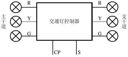
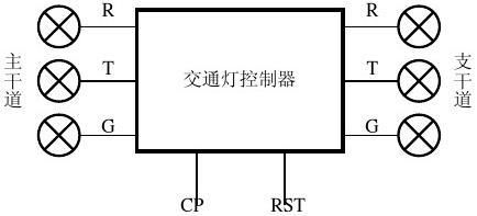
a)系统框图
b)状态转换说明:主干道和支干道永远有且只有一个灯亮,紧急路况时两边红灯亮,其
余时候有且只有一个红灯亮;主干道绿灯、主干道转向灯亮、支干道绿灯、支干道转向灯依次亮,在最后t0S(默认为5S)闪烁。
c)输入输出及信号设计:
Port ( LCD_Clk : in STD_LOGIC;----50mhz时钟
reset : in STD_LOGIC:='0';--复位
sensor:in std_logic :='0';---特殊情况时,两边都是红灯
up:in std_logic :='0' ;---有效时调整时间时增大时间
down:in std_logic :='0';---有效时调整时间时减少时间
choose:in std_logic :='0';---选择调整哪一个时间
control:in std_logic :='0';---有效时可以暂停,调整时间
LCD_RS : out STD_LOGIC;
LCD_RW : out STD_LOGIC;
LCD_EN : out STD_LOGIC;
redax,greenax ,greenay:out std_logic;--主干道的红灯和两个绿灯,greenay为
左转灯
redbx,greenbx ,greenby:out std_logic;--支干道的红灯和两个绿灯,greenby为左转灯 data : out STD_LOGIC_VECTOR (3 downto 0)); --Lcd显示
type istate is(
write_instr,
write_dataup4,
write_datadown4,
set_addrup,
set_addrdown,
ret_homeup,
ret_homedown
);
signal state:istate;
2
signal cnt_clk,clk500:std_logic;---分别为1hz,500hz
signal cnt:integer range 0 to 15:=0;
signal cntnumh,cntnuml:integer range 0 to 9;--输入到数码管的数字
signal countnum:integer ;---计数器
signal reda,greena,greena1,redb,greenb,greenb1:std_logic;--各交通灯对应的信? signal t:integer range 0 to 99;---要输入lcd中的数字
d)基本模块设计:
1)字符译码函数
function putc(data:character) return std_logic_vector is
---字符译码函数,将字符显示在lcd上
variable result:std_logic_vector(7 downto 0);
begin
case data is
when 'o'=> result:=conv_std_logic_vector(111,8);
when 'u'=> result:=conv_std_logic_vector(117,8);
when 'C'=> result:=conv_std_logic_vector(67,8);
when 'n'=> result:=conv_std_logic_vector(110,8);
when 't'=> result:=conv_std_logic_vector(116,8);
when 'e'=> result:=conv_std_logic_vector(101,8);
when 'r'=> result:=conv_std_logic_vector(114,8);
when ':'=> result:=conv_std_logic_vector(58,8);
when others => result:=conv_std_logic_vector(32,8);
end case;
return result;
end putc;
2)数字译码函数
function putn(num:in integer range 0 to 9) return std_logic_vector is
---数字译码函数,将数字显示在lcd上
variable fig:std_logic_vector(7 downto 0);
begin
case num is
when 0=> fig:="00110000";
when 1=> fig:="00110001";
when 2=> fig:="00110010";
when 3=> fig:="00110011";
when 4=> fig:="00110100";
when 5=> fig:="00110101";
when 6=> fig:="00110110";
when 7=> fig:="00110111";
when 8=> fig:="00111000";
when 9=> fig:="00111001";
end case;
return fig;
end putn;
3
3)分频,由50Mhz得到500hz,驱动lcd
process(LCD_Clk)
----分频,得到500hz时钟
variable n3:integer range 0 to 49999;
begin
if rising_edge(LCD_Clk) then
if n3<49999 then
n3:=n3+1;
else
n3:=0;
clk500<=not clk500;
end if;
end if;
end process;
4)分频,由500hz得到1hz,作为交通灯控制器输入
process(clk500)
----分频,得到1hz时钟
variable n:integer range 0 to 249;
begin
if rising_edge(clk500) then
if n<249 then
n:=n+1;
else
n:=0;
cnt_clk<=not cnt_clk;
end if;
end if;
end process;
5)主要功能实现:
process(cnt_clk,reset,choose,up,down,control,t)
---实现各种要求功能,包括倒计时显示,红绿灯(含左转灯)转换,以及转换时间调整
variable m:integer range 0 to 4 ;---m表示转换的是哪一个时间(t0-t4中哪一个) variable count : natural range 0 to 99;---计数器,将正计数转换为倒计数 variable t0:integer range 0 to 99 :=5;---绿灯闪烁时间
variable t1:integer range 0 to 99 :=79;---主干道绿灯亮的时间
variable t2:integer range 0 to 99 :=20;---主干道左转灯亮的时间
variable t3:integer range 0 to 99:=20;---支干道绿灯亮的时间
variable t4:integer range 0 to 99:=10;---支干道左转灯亮的时间
begin
if reset='1' then --1
----复位,计数器清零,m,t0-t4赋初值
countnum<=0;
m:=0;
4
t0:=5; t1:=79; t2:=20; t3:=20; t4:=10;
elsif control='1' then--可调节时间或暂停
if rising_edge(cnt_clk) then --2
if choose ='1' then –选择t0-t4中的哪一个 3
if m=4 then --4
m:=0;---m在0-4之间循环
else
m:=m+1;
end if; --4
t<=m;--显示m
else --choose为0时调节所选时间 3
if up='1' then --tx增大 --4
if m =0 then --调整t0,即闪烁时间,上限为7s, if t0=7 then --6
t0:=5;
else
t0:=t0+1;
end if; --6
t<=t0;--显示t0
elsif m=1 then--调整t1,上限99s
if t1=99 then --6
t1:=79;
else
t1:=t1+1;
end if; --6
t<=t1;--显示t1
elsif m=2 then--调整t2,上限为30s
if t2=30 then --6
t2:=20;
else
t2:=t2+1;
end if; --6
t<=t2;--显示t2
elsif m=3 then --调整t3,上限为30s
if t3=30 then --6
t3:=20;
else
t3:=t3+1;
end if; --6
t<=t3;--显示t3 5
5
elsif m=4 then--调整t4,上限为15s
if t4=15 then --6
t4:=10;
else
t4:=t4+1;
end if; --6
t<=t4;--显示t4
end if; --5
elsif down='1' then --tx减小 4
if m =0 then ----调整t0,即闪烁时间,下限为2s, if t0=2 then --6
t0:=5;
else t0:=t0-1;
end if; --6
t<=t0;---显示t0
elsif m=1 then----调整t1,下限为39秒
if t1=39 then --6
t1:=79;
else t1:=t1-1;
end if; --6
t<=t1;--显示t1
elsif m=2 then ----调整t2,下限为10s
if t2=10 then --6
t2:=20;
else t2:=t2-1;
end if; --6
t<=t2;---显示t2
elsif m=3 then -----调整t3,下限10s
if t3=10 then --6
t3:=20;
else t3:=t3-1;
end if;--6
t<=t3;---显示t3
elsif m=4 then----调整t4,下限8s
if t4=8 then --6
t4:=10;
else t4:=t4-1;
end if;--6
t<=t4; --显示t4
end if; --5
end if; --4
end if; --3
end if; --2
elsif rising_edge(cnt_clk) then --此时reset=0 5
6
if countnum=t1+t2+t3+t4 then --2记数到整周期时,记数器清零
countnum<=0;
else
countnum<=countnum+1; ---计数器小于整周期时,正常记数 end if; --2
if sensor='1' then --2 sensor信号有效期间,表示紧急情况两组路灯都为红灯
reda<='1';
redb<='1';
greena<='0';
greenb<='0';
greena1<='0';
greenb1<='0';
else
if countnum<=t1-t0 then--3主干道绿灯亮且非闪烁,支干道红灯亮
reda<='0';
greena<='1';
greena1 <= '0';
redb<='1';
greenb<='0';
greenb1<='0';
elsif countnum<=t1 then --主干道绿灯亮且闪烁,支干道红灯亮 reda<='0';
greena<=not greena;
greena1<= '0';
redb<='1';
greenb<='0';
greenb1<='0';
elsif countnum<=t1+t2-t0 then --主干道左转绿灯亮且非闪烁,支干道红灯亮
reda<='0';
greena<='0';
greena1 <= '1';
redb<='1';
greenb<='0';
greenb1<='0';
elsif (countnum<=t1+t2) then --主干道左转绿灯亮且闪烁,支干道红亮
reda<='0';
greena<='0';
greena1 <= not greena1;
redb<='1';
7
greenb<='0';
greenb1<='0';
elsif (countnum<=t1+t2+t3-t0) then --支干道绿灯亮且非闪烁,主干道红灯亮
reda<='1';
greena<='0';
greena1 <= '0';
redb<='0';
greenb<='1';
greenb1<='0';
elsif (countnum<=t1+t2+t3) then --支干道绿灯亮且闪烁,主干道红灯亮
reda<='1';
greena<='0';
greena1 <= '0';
redb<='0';
greenb<=not greenb;
greenb1<='0';
elsif (countnum<=t1+t2+t3+t4-t0) then --支干道左转绿灯亮且非闪烁,主干道红灯亮
reda<='1';
greena<='0';
greena1 <= '0';
redb<='0';
greenb<='0';
greenb1<='1';
elsif (countnum<=t1+t2+t3+t4) then --支干道左转绿灯亮且闪烁,主干道红灯亮
reda<='1';
greena<='0';
greena1 <= '0';
redb<='0';
greenb<='0';
greenb1<=not greenb1;
end if; --3
end if; --2
----下面将正计数转换为倒计数-----
if countnum<=t1 then --2
count:=t1-countnum; ---主干道绿灯亮,支干道红灯亮时倒计时 elsif countnum<=t1+t2 then ---主干道左转绿灯亮,支干道红灯亮时倒计时
count:=t1+t2-countnum;
elsif countnum<=t1+t2+t3 then----支干道绿灯亮,主干道红灯亮 时倒计时
8
count:=t1+t2+t3-countnum;
elsif countnum<=t1+t2+t3+t4 then---支干道左转绿灯亮,主干道红灯亮 时倒计时
count:=t1+t2+t3+t4-countnum;
end if; --2
----上面将正计数转换为倒计数----
t<=count;---显示count
end if; --1
-----以下代码为分位译码-----
if t>=90 then --1
cntnumh<=9;
cntnuml<=t-90;
elsif t>=80 then
cntnumh<=8;
cntnuml<=t-80;
elsif t>=70 then
cntnumh<=7;
cntnuml<=t-70;
elsif t>=60 then
cntnumh<=6;
cntnuml<=t-60;
elsif t>=50 then
cntnumh<=5;
cntnuml<=t-50;
elsif t>=40 then
cntnumh<=4;
cntnuml<=t-40;
elsif t>=30 then
cntnumh<=3;
cntnuml<=t-30;
elsif t>=20 then
cntnumh<=2;
cntnuml<=t-20;
elsif t>=10 then
cntnumh<=1;
cntnuml<=t-10;
else
cntnumh<=0;
cntnuml<=t;
end if;--1
-----以上代码为分位译码-----
---各信号赋给各输出的交通灯
greenax<=greena;----主干绿灯
greenay<=greena1;---主干左转绿灯
9
greenbx<=greenb;---支干道绿灯
greenby<=greenb1;---支干道左转绿灯
redax<=reda;----主干红灯
redbx<=redb;--支干道绿灯
end process;
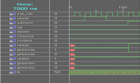
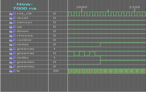
主要功能仿真如下:
a)、reset为1时,初始化。为0时,会从79倒计时,主干道绿灯亮,支干道红灯亮,sensor为1时,主干道和支干道都为红灯亮:
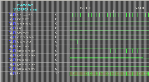
b)默认情况下倒计时到最后5S时会闪烁显示,并切换到下一状态,继续倒
计时:
10
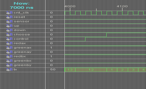
c)如果reset=0且control为1时,暂停计数,此时若choose为1,则会在0-4之间循环计数,选择调节哪一个时间(t0-t4),若choose改为0,就会暂停计数:
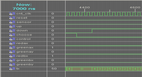
d)此时(reset=0,control=1,choose=0)若选择down=1或up=1,则会减计数(默认值到最小值循环)或加计数(默认值到最大值循环)调整当前选中的时间t:(当前选的t0,闪烁时间,最后调整为7s)
e)若将control置于0 ,则会接着倒计时,就像最初初始化时,但此时调整后的时间生效(这里闪烁时间改为7s):
11
6)显示
process(clk500,reset)
------lcd上显示数字和字符
begin
if reset='1' then---复位时不显示
state<=write_instr;
LCD_RS<='0';
cnt<=0;
elsif rising_edge(clk500) then---显示数字或字符 case state is
when write_instr=>
LCD_RS<='0';
case cnt is
when 0=> data<="0011"; when 1=> data<="0011"; when 2=> data<="0011"; when 3=> data<="0010";
when 4=> data<="0010"; when 5=> data<="1000";
when 6=> data<="0000"; when 7=> data<="0110";
when 8=> data<="0000"; when 9=> data<="1100";
when 10=> data<="0000"; when 11=> data<="0001";
12
when others=> data<="0000"; end case; if cnt=11 then cnt<=0; state<=write_dataup4; else cnt<=cnt+1; state<=write_instr;
end if;
when write_dataup4=>
LCD_RS<='1';
case cnt is
when 0=> data<=putc('C')(7 downto 4); when 1=> data<=putc('o')(7 downto 4); when 2=> data<=putc('u')(7 downto 4); when 3=> data<=putc('n')(7 downto 4); when 4=> data<=putc('t')(7 downto 4); when 5=> data<=putc('e')(7 downto 4); when 6=> data<=putc('r')(7 downto 4); when 7=> data<=putc(':')(7 downto 4);
when 8=> data<=putn(cntnumh)(7 downto 4); when 9=> data<=putn(cntnuml)(7 downto 4); when others=>data<="0000";
end case;
state<=write_datadown4;
when write_datadown4=>
case cnt is
when 0=> data<=putc('C')(3 downto 0); when 1=> data<=putc('o')(3 downto 0); when 2=> data<=putc('u')(3 downto 0); when 3=> data<=putc('n')(3 downto 0); when 4=> data<=putc('t')(3 downto 0); when 5=> data<=putc('e')(3 downto 0); when 6=> data<=putc('r')(3 downto 0); when 7=> data<=putc(':')(3 downto 0);
when 8=> data<=putn(cntnumh)(3 downto 0); when 9=> data<=putn(cntnuml)(3 downto 0); when others=>data<="0000";
end case;
if cnt=7 then
cnt<=8;
state<=set_addrup;
elsif cnt=9 then
13
cnt<=0;
state<=ret_homeup; else
cnt<=cnt+1;
state<=write_dataup4; end if;
when set_addrup=> LCD_RS<='0'; data<="1100";
state<=set_addrdown; when set_addrdown=> data<="0111";
state<=write_dataup4; when ret_homeup=> LCD_RS<='0'; data<="0000";
state<=ret_homedown; when ret_homedown=> data<="0010";
state<=write_dataup4; when others=>
state<=write_instr; end case;
end if;
end process;
end Behavioral;
五、位置约束、下载与配置
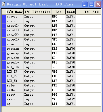
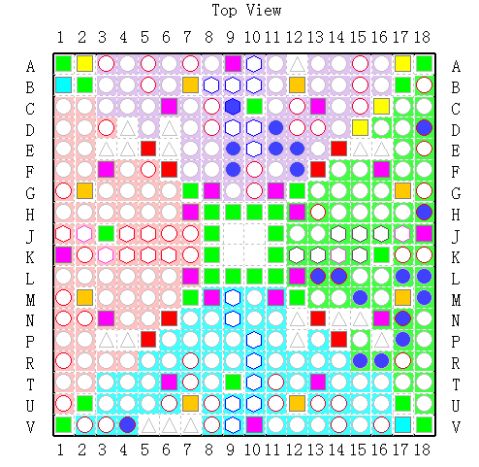
最终,在实验板正常运行,实现所有功能。 14
实验小结:
a) 心得体会
通过这次实验,我进一步掌握了VHDL语言的一些常用的语法规则,熟悉了ISE软件的使用,对Spartan 3E开发板有了更深的认识,了解了管脚的分配和FPGA的下载和配置方法。通过对于交通灯的设计,我学会了如何写LCD驱动,对于FPGA较深了兴趣。
b) 待改进的问题
1、模块化做的不够好,主要功能都在同一个进程里实现,使得代码可读性不够强;
2、基本功能完成之后才开始实现扩展功能,只是对源代码的修改、添加新内容,整个程序逻辑不够明确,没有在最开始规划好;
3、所有时间的调节都是同步的,需要时钟配合,可以改进为按键调节;
4、程序中很多命名不够规范。
c) 功能扩展
1、 添加了紧急路况处理功能;
2、 实现了各灯亮的时间以及闪烁时间的调整。
15