福州大学
《嵌入式系统设计课设》
报告书
题 目:基于28027的虚拟系统
姓 名:
学 号:
学 院: 电气工程与自动化学院
专 业: 电气工程与自动化
年 级:
起讫日期:
指导教师:
目 录
1、课程设计目的............................................................................................................. 1
2、课程设计题目和实现目标............................................................................................ 1
3、设计方案................................................................................................................. 1
4、程序流程图............................................................................................................. 1
5、程序代码................................................................................................................. 1
6、调试总结.................................................................................................................. 1
7、设计心得体会......................................................................................................... 1
8、参考文献................................................................................................................. 1
1、课程设计目的
《嵌入式系统设计课设》是与《嵌入式系统设计》课程相配套的实践教学环节。《嵌入式系统设计》是一门实践性很强的专业基础课,通过课程设计,达到进一步理解嵌入式芯片的硬件、软件和综合应用方面的知识,培养实践能力和综合应用能力,开拓学习积极性、主动性,学会灵活运用已经学过的知识,并能不断接受新的知识。培养大胆发明创造的设计理念,为今后就业打下良好的基础。
通过课程设计,掌握以下知识和技能:
1.嵌入式应用系统的总体方案的设计;
2.嵌入式应用系统的硬件设计;
3.嵌入式应用系统的软件程序设计;
4.嵌入式开发系统的应用和调试能力
2、课程设计题目和实现目标
课程设计题目:基于28027的虚拟系统
任务要求:
A、利用28027的片上温度传感器,检测当前温度;
B、 通过PWM过零中断作为温度检测A/D的触发,在PWM中断时完成温度采样和下一周期PWM占空比的修正;PWM频率为1K;
C、 利用按键作为温度给定;温度给定变化从10度到40度。
D、当检测温度超过给定时,PWM占空比增减小(减小幅度自己设定);当检测温度小于给定时,PWM占空比增大(增大幅度自己设定);
E、 把PWM输出接到捕获口,利用捕获口测量当前PWM的占空比;
F、 把E测量的PWM占空比通过串口通信发送给上位机;
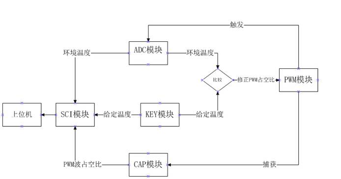
3、设计方案-----介绍系统实现方案和系统原理图
①系统实现方案:
任务A:利用ADC模块通道A5获取当前环境温度。
任务B:PWM过零触发ADC模块,在PWM中断服务函数中,将当前环境温度和按键设定温度进行比较,并按照任务D的要求修订PWM占空比。
PWM频率为1K HZ:
根据关系式:TBCLK=SYSCLKOUT/(HSPCLKDIV*CLKDIV)
取SYSCLKOUT=60M HZ,HSPCLKDIV=6,CLKDIV=1,求得
TBCLK=10M HZ。将period设为10K,便得到1K HZ 的PWM波。
任务C:用KEY模块的中断实现温度给定。
任务D:在PWM的周期结束产生的中断中,通过改变比较点CMPA的位置来改变PWM占空比的大小。
任务E:利用CAP模块设置3个捕获点捕获PWM的上升沿和下降沿,计算得到PWM波的占空比。
任务F:利用SCI模块实现串口通信将温度和占空比上传到上位机。
此外,各模块的配置都与GPIO模块有关。
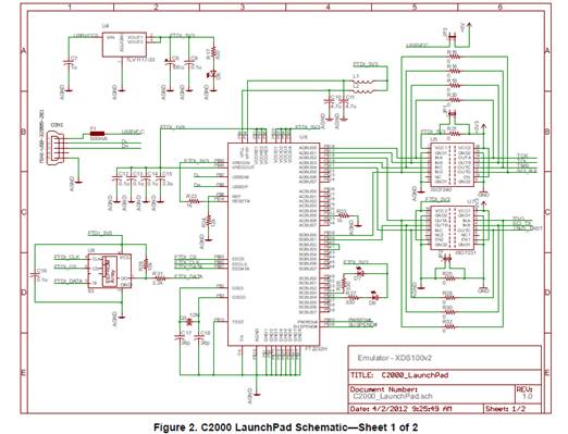
②系统原理图:28027 C2000 Piccolo Launchpad原理图

4、程序流程--------各个模块的流程图
5、程序代码

①/*app.c*/
// the includes
#include "Application/app.h"
// **************************************************************************
// the defines
// **************************************************************************
// the globals
// **************************************************************************
// the functions
voiddelay(uint32_t time)
{
while(time--);
}
//延时函数
// end of file
②/*isr.c*/
// the includes
#include "Application/isr.h"
// **************************************************************************
// the defines
// **************************************************************************
// the globals
// **************************************************************************
// the functions
interruptvoidLED_PWM_isr(void) //PWM的中断服务函数
{
if(MY_ADC<SET_TEMP) //环境检测温度小于设定温度时
{
mycmp-=100*(SET_TEMP-MY_ADC); //PWM占空比增大
}
else
{
mycmp+=100*(MY_ADC-SET_TEMP); //环境检测温度大于设定温度
// PWM占空比减小
}
PWM_setCmpA(myPwm1,mycmp); //设定CmpA值
PWM_clearIntFlag(myPwm1); //清零PWM中断标志位
PIE_clearInt(myPie,PIE_GroupNumber_3); //清零PIE中断标志位
mycmp=5000; //将比较点初值设为5000
}
interruptvoidMY_ADC_isr(void) //ADC中断服务函数
{ MY_ADC=ADC_readResult(myAdc,ADC_ResultNumber_0);
//获取ADC转换的数字量
MY_ADC= ADC_getTemperatureC(myAdc, MY_ADC);
//将数字量转换为温度值
ADC_clearIntFlag(myAdc, ADC_IntNumber_1);
//清除中断标志位
PIE_clearInt(myPie,PIE_GroupNumber_10);
}
interruptvoidKEY_xint1_isr(void) //按键中断服务函数
{
SET_TEMP++;
if(SET_TEMP>40)
{
SET_TEMP=10;
}
PIE_clearInt(myPie,PIE_GroupNumber_1);
}
interruptvoidMY_CAP_isr(void) //CAP中断服务函数
{
uint32_t CapEvent1Count=0,CapEvent2Count=0,CapEvent3Count=0;
float fPwmDuty=0.0;
CapEvent1Count = CAP_getCap1(myCap);
CapEvent2Count = CAP_getCap2(myCap);
CapEvent3Count = CAP_getCap3(myCap);
fPwmDuty = (float)(CapEvent2Count - CapEvent1Count) / (CapEvent3Count - CapEvent1Count); //计算PWM占空比
fPwmDuty=fPwmDuty*100;
NOW_PWM=(int)fPwmDuty;
CAP_clearInt(myCap, CAP_Int_Type_CEVT3);
CAP_clearInt(myCap, CAP_Int_Type_Global);
// Acknowledge this interrupt to receive more interrupts from group 4
PIE_clearInt(myPie, PIE_GroupNumber_4);
}
//redefined in Isr.h
// end of file

①/*F2802x_Device.h*/
#include "F2802x_Component/include/adc.h"
#include "F2802x_Component/include/clk.h"
#include "F2802x_Component/include/flash.h"
#include "F2802x_Component/include/gpio.h"
#include "F2802x_Component/include/pie.h"
#include "F2802x_Component/include/pll.h"
#include "F2802x_Component/include/timer.h"
#include "F2802x_Component/include/wdog.h"
#include "F2802x_Component/include/sci.h"
#include "F2802x_Component/include/cap.h"
①/*Key.c*/
// the includes
#include "User_Component/Key/Key.h"
// **************************************************************************
// the defines
// **************************************************************************
// the globals
// **************************************************************************
// the functions
// the function prototypes
//! \brief KEY initail
//! \param[in] None
//! \param[out] None
voidKEY_initial(void)
{
}
//
//! \brief KEY configure
//! \param[in] None
//! \param[out] None
voidKEY_config(void)
{ //按键为GPIO12设置为输入口
//1. mode
GPIO_setMode(KEY_obj, KEY1, GPIO_12_Mode_GeneralPurpose);
//2. direction
GPIO_setDirection(KEY_obj, KEY1, GPIO_Direction_Input);
//3. pullup
GPIO_setPullUp(KEY_obj, KEY1, GPIO_PullUp_Disable);
//4. qualification
GPIO_setQualification(KEY_obj, KEY1, GPIO_Qual_Sync);
}
//! \brief ScanKey API
//! \param[in] key
//! \param[out] the state of KEY
uint16_t ScanKey(const GPIO_Number_e key)
{
return GPIO_getData(KEY_obj, key);
}
//! \param[in] None
//! \param[out] None
voidKEY_INT_config(void)
{ //(3). register PIR vector
PIE_registerPieIntHandler(myPie, PIE_GroupNumber_1, PIE_SubGroupNumber_4, (intVec_t) &KEY_xint1_isr);
//(4). module interrupt configure
PIE_setExtIntPolarity(myPie,CPU_ExtIntNumber_1, PIE_ExtIntPolarity_FallingEdge);
GPIO_setExtInt(myGpio, GPIO_Number_12, CPU_ExtIntNumber_1);
//(5). enable module IE
PIE_enableExtInt(myPie, CPU_ExtIntNumber_1);
//(6). enable PIEIERx.y
PIE_enableInt(myPie, PIE_GroupNumber_1, PIE_InterruptSource_XINT_1);
//(7) enable CPU IERx
CPU_enableInt(myCpu, CPU_IntNumber_1);
}
//
//! \brief Interrupt Service Routine
//! \param[in] None
//! \param[out] None
TARGET_EXT interruptvoidKEY_xint1_isr(void); //redefined in Isr.h
// end of file
/*Key.h*/
#ifndef _KEY_H_
#define _KEY_H_
// the includes
#include <stdint.h>
// driver
#include "F2802x_Component/F2802x_Device.h"
#include "User_Component/User_Mcu/User_System.h"
#ifdef __cplusplus
extern "C" {
#endif
#ifndef TARGET_GLOBAL
#define TARGET_EXT extern
#else
#define TARGET_EXT
#endif
/*------- hardware description of the example module -------------*/
// For example
// The module derived from GPIO
#define KEY_obj myGpio //here myGpio is defined in System.h
#define KEY1 GPIO_Number_12 //pin
TARGET_EXT voidKEY_initial(void);
TARGET_EXT voidKEY_config(void);
TARGET_EXT voidKEY_INT_config(void);
TARGET_EXT interruptvoidKEY_xint1_isr(void); //redefined in Isr.h
/*-------end of hardware description -------------*/
TARGET_EXT uint16_t ScanKey(const GPIO_Number_e key);
/*-------end of API description -------------*/
#define KEYPressed 1
/*------- end of defines -------------*/
#ifdef __cplusplus
}
#endif // extern "C"
#endif // end of _EXAMPLE_H_ definition
②/*LED_PWM.c*/
// the includes
#include "User_Component/LED_PWM/LED_PWM.h"
// the functions
voidLED_PWM_initial(void)
{
mycmp=0;
}
voidLED_PWM_config(void)
{
//GPIO的配置
GPIO_setMode(myGpio,GPIO_Number_0,GPIO_0_Mode_EPWM1A);
GPIO_setPullUp(myGpio,GPIO_Number_0,GPIO_PullUp_Disable);
//PWM的配置
CLK_disableTbClockSync(myClk);
//PWM模块使能
CLK_enablePwmClock(myClk,PWM_Number_1);
//设置PWM的时钟
//PWM_setClkDiv(myPwm1,PWM_ClkDiv_by_1);
PWM_setHighSpeedClkDiv(myPwm1, PWM_HspClkDiv_by_6);
//计数器的设置
PWM_setCounterMode(myPwm1,PWM_CounterMode_Up);
//PWM周期设置
PWM_setPeriod(myPwm1,10000);
//设置周期加载模式
PWM_setPeriodLoad(myPwm1,PWM_PeriodLoad_Shadow);
//比较点的设置
PWM_setCmpA(myPwm1,5000);
//PWM装载模式
PWM_setLoadMode_CmpA(myPwm1,PWM_LoadMode_Period);
//动作
PWM_setActionQual_CntUp_CmpA_PwmA(myPwm1,PWM_ActionQual_Set);
PWM_setActionQual_Period_PwmA(myPwm1,PWM_ActionQual_Clear);
//时钟同步
CLK_enableTbClockSync(myClk);
}
voidLED_PWM_INT_config(void)
{
PIE_registerPieIntHandler(myPie,PIE_GroupNumber_3,PIE_SubGroupNumber_1,(intVec_t)&(LED_PWM_isr));
//模块中断配置
PWM_setIntMode(myPwm1,PWM_IntMode_CounterEqualPeriod);
PWM_setIntPeriod(myPwm1,PWM_IntPeriod_FirstEvent);
//PWM中断使能
PWM_enableInt(myPwm1);
//PIE开关的允许
PIE_enableInt(myPie, PIE_GroupNumber_3, PIE_InterruptSource_EPWM1);
//CPU全局中断
CPU_enableInt(myCpu,CPU_IntNumber_3);
}
// end of file
/LED_PWM.h*/
#ifndef _LED_PWM_H_
#define _LED_PWM_H_
// the includes
#include <stdint.h>
// driver
#include "F2802x_Component/F2802x_Device.h"
#include "User_Component/User_Mcu/User_System.h"
#ifdef __cplusplus
extern "C" {
#endif
#ifndef TARGET_GLOBAL
#define TARGET_EXT extern
#else
#define TARGET_EXT
#endif
/*------- hardware description of the example module -------------*/
TARGET_EXT voidLED_PWM_initial(void);
TARGET_EXT voidLED_PWM_config(void);
TARGET_EXT voidLED_PWM_INT_config(void);
TARGET_EXT interruptvoidLED_PWM_isr(void); //redefined in Isr.h
/*-------end of hardware description -------------*/
TARGET_EXT uint16_t mycmp;
#ifdef __cplusplus
}
#endif // extern "C"
#endif // end of _EXAMPLE_H_ definition
③/*MY_ADC.c*/
// the includes
#include "User_Component/MY_ADC/MY_ADC.h"
// the functions
voidMY_ADC_initial(void)
{
SET_TEMP=30; //初始设定温度为30摄氏度
}
voidMY_ADC_config(void)
{ //ADC时钟使能
CLK_enableAdcClock(myClk);
//初始化ADC模块
ADC_setVoltRefSrc(myAdc, ADC_VoltageRefSrc_Int);
ADC_powerUp(myAdc);
ADC_enableBandGap(myAdc);
ADC_enableRefBuffers(myAdc);
ADC_enable(myAdc);
//温度转换使能
ADC_enableTempSensor(myAdc);
//soc配置
ADC_setSocChanNumber(myAdc, ADC_SocNumber_0, ADC_SocChanNumber_A5);
ADC_setSocSampleWindow(myAdc, ADC_SocNumber_0, ADC_SocSampleWindow_7_cycles);
ADC_setSocTrigSrc(myAdc, ADC_SocNumber_0, ADC_SocTrigSrc_EPWM1_ADCSOCA);
//PWM配置
PWM_setSocAPulseSrc(myPwm1,PWM_SocPulseSrc_CounterEqualZero);
PWM_setSocAPeriod(myPwm1,PWM_SocPeriod_FirstEvent);
PWM_enableSocAPulse(myPwm1);
}
voidMY_ADC_INT_config(void)
{
PIE_registerPieIntHandler(myPie,PIE_GroupNumber_10,PIE_SubGroupNumber_1,(intVec_t)&(MY_ADC_isr));
//模块中断配置
ADC_setIntPulseGenMode(myAdc, ADC_IntPulseGenMode_Prior);
ADC_setIntSrc(myAdc,ADC_IntNumber_1, ADC_IntSrc_EOC0);
ADC_setIntMode(myAdc, ADC_IntNumber_1, ADC_IntMode_ClearFlag);
//ADC中断使能
ADC_enableInt(myAdc,ADC_IntNumber_1);
//PIE开关的允许
PIE_enableInt(myPie, PIE_GroupNumber_10, PIE_InterruptSource_ADCINT_10_1);
//CPU全局中断
CPU_enableInt(myCpu,CPU_IntNumber_10);
}
// end of file
/*MY_ADC.h*/
#ifndef _MY_ADC_H_
#define _MY_ADC_H_
// the includes
#include <stdint.h>
// driver
#include "F2802x_Component/F2802x_Device.h"
#include "User_Component/User_Mcu/User_System.h"
#ifdef __cplusplus
extern "C" {
#endif
#ifndef TARGET_GLOBAL
#define TARGET_EXT extern
#else
#define TARGET_EXT
#endif
/*------- hardware description of the example module -------------*/
TARGET_EXT voidMY_ADC_initial(void);
TARGET_EXT voidMY_ADC_config(void);
TARGET_EXT voidMY_ADC_INT_config(void);
TARGET_EXT interruptvoidMY_ADC_isr(void); //redefined in Isr.h
/*-------end of hardware description -------------*/
TARGET_EXT uint16_t MY_ADC;
TARGET_EXT uint16_t SET_TEMP;
/*------- end of globals -------------*/
#ifdef __cplusplus
}
#endif // extern "C"
#endif // end of _EXAMPLE_H_ definition
④/*MY_CAP.c*/
// the includes
#include "User_Component/MY_CAP/MY_CAP.h"
#include "User_Component/User_Mcu/User_System.h"
voidMY_CAP_initial(void)
{
}
voidMY_CAP_config(void)
{
GPIO_setPullUp(myGpio, GPIO_Number_5, GPIO_PullUp_Enable);
GPIO_setQualification(myGpio, GPIO_Number_5, GPIO_Qual_Sync);
GPIO_setMode(myGpio, GPIO_Number_5, GPIO_5_Mode_ECAP1);
CLK_enableEcap1Clock(myClk);
CAP_disableInt(myCap, CAP_Int_Type_All); // 禁止CAP中断 CAP_clearInt(myCap, CAP_Int_Type_All); // 清除CAP中断标志位 CAP_disableCaptureLoad(myCap); // Disable CAP1-CAP4 register loads
CAP_disableTimestampCounter(myCap); // Make sure the counter is stopped
// Configure peripheral registers
CAP_setCapContinuous(myCap); // continuous
CAP_setStopWrap(myCap, CAP_Stop_Wrap_CEVT4);// Stop at 3 events
CAP_setCapEvtPolarity(myCap, CAP_Event_1, CAP_Polarity_Rising); // 捕获上升沿
CAP_setCapEvtPolarity(myCap, CAP_Event_2, CAP_Polarity_Falling); // 捕获下降沿
CAP_setCapEvtPolarity(myCap, CAP_Event_3, CAP_Polarity_Rising); // 捕获上升沿
CAP_setCapEvtReset(myCap, CAP_Event_3, CAP_Reset_Enable); // 重置计数器确保计数器不会溢出 CAP_enableTimestampCounter(myCap); // 打开计数器
CAP_enableCaptureLoad(myCap); // Enable CAP1-CAP4 register loads
/* CAP_enableInt(myCap, CAP_Int_Type_CEVT3); // 3个捕获点之后发生中断
// Register interrupt handlers in the PIE vector table
PIE_registerPieIntHandler(myPie, PIE_GroupNumber_4, PIE_SubGroupNumber_1, (intVec_t)&ecap1_isr);
// Enable CPU INT4 which is connected to ECAP1-4 INT:
CPU_enableInt(myCpu, CPU_IntNumber_4);
// Enable eCAP INTn in the PIE: Group 3 interrupt 1-6
PIE_enableCaptureInt(myPie);
CPU_enableGlobalInts(myCpu);
*/
}
voidMY_CAP_INT_config(void)
{
CAP_enableInt(myCap, CAP_Int_Type_CEVT3); // 3 events = interrupt
// Register interrupt handlers in the PIE vector table
PIE_registerPieIntHandler(myPie, PIE_GroupNumber_4, PIE_SubGroupNumber_1, (intVec_t)&MY_CAP_isr);
// Enable CPU INT4 which is connected to ECAP1-4 INT:
CPU_enableInt(myCpu, CPU_IntNumber_4);
// Enable eCAP INTn in the PIE: Group 3 interrupt 1-6
PIE_enableCaptureInt(myPie);
CPU_enableGlobalInts(myCpu);}
// end of file
/*MY_CAP.h*/
#ifndef _MY_CAP_H_
#define _MY_CAP_H_
// the includes
#include <stdint.h>
// driver
#include "F2802x_Component/F2802x_Device.h"
#ifdef __cplusplus
extern "C" {
#endif
#ifndef TARGET_GLOBAL
#define TARGET_EXT extern
#else
#define TARGET_EXT
#endif
/*------- hardware description of the example module -------------*/
TARGET_EXT voidMY_CAP_initial(void);
TARGET_EXT voidMY_CAP_config(void);
TARGET_EXT voidMY_CAP_INT_config(void);
TARGET_EXT interruptvoidMY_CAP_isr(void); //redefined in Isr.h
/*-------end of hardware description -------------*/
TARGET_EXT int NOW_PWM;
#ifdef __cplusplus
}
#endif // extern "C"
#endif // end of _EXAMPLE_H_ definition
⑤/*mySci.c*/
// the includes
#include "User_Component/mySci/mySci.h"
// the functions
// the function prototypes
//! \brief SCI initail
//! \param[in] None
//! \param[out] None
voidSCI_initial(void)
{
}
//
//! \brief SCI configure
//! \param[in] None
//! \param[out] None
voidSCI_config(void)
{ //1. GPIO configure
//1.1 pullup
GPIO_setPullUp(myGpio, GPIO_Number_28, GPIO_PullUp_Enable);
GPIO_setPullUp(myGpio, GPIO_Number_29, GPIO_PullUp_Disable);
//1.2 input qualification
GPIO_setQualification(myGpio, GPIO_Number_28, GPIO_Qual_ASync);
//1.3 mode
GPIO_setMode(myGpio, GPIO_Number_28, GPIO_28_Mode_SCIRXDA);
//SCI数据发送引脚
GPIO_setMode(myGpio, GPIO_Number_29, GPIO_29_Mode_SCITXDA);
//SCI数据接收引脚
//2. enable SCIA clk
CLK_enableSciaClock(myClk);
//3. configure the low speed peripheral clock(LSPCLK) LSPCLK = SYSCLKOUT/4 =15MHz
CLK_setLowSpdPreScaler(myClk, CLK_LowSpdPreScaler_SysClkOut_by_4);
//设置时钟分频
//4. SCI BRR = LSPCLK/(SCI BAUDx8) - 1
SCI_setBaudRate(mySci, SCI_BaudRate_9_6_kBaud);
//设置波特率为9600
//5. configure package(1 stop bit, No loopback, No parity,8 char bits, async mode, idle-line protocol)
SCI_disableParity(mySci);
SCI_setNumStopBits(mySci, SCI_NumStopBits_One);
SCI_setCharLength(mySci, SCI_CharLength_8_Bits);
//6. enable SCI TX&RX
SCI_enableTx(mySci);
SCI_enableRx(mySci);
//7.configure the SCI TX&RX FIFO
//7.1 enable FIFO
//先进先出
SCI_resetChannels(mySci);
SCI_enableFifoEnh(mySci);
//7.2 configure TX FIFO
SCI_resetTxFifo(mySci);
//7.3 configure RX FIFO
SCI_resetRxFifo(mySci);
//8. enable SCI module
SCI_enable(mySci);
}
//! \brief Transmit a string from the SCI
//! \param[in] string
//! \param[out] None
voidscia_msg(char * msg)
{
int i;
i = 0;
while(msg[i] != '\0')
{
scia_xmit(msg[i]);
i++;
}
}
//! \brief Transmit a char from the SCI
//! \param[in] char
//! \param[out] None
voidscia_xmit(int a)
{
while(SCI_getTxFifoStatus(mySci) != SCI_FifoStatus_Empty) {}
SCI_putDataBlocking(mySci, a);
}
//! \brief Receive a char from the SCI
//! \param[in] None
//! \param[out] a:receive data
//! 00: no received /00: received
intscia_receive(uint16_t *a)
{
if(SCI_getRxFifoStatus(mySci) < SCI_FifoStatus_1_Word)
{ return 0;
}
else
{
*a = SCI_getData(mySci);
}
return 1;
}
// end of file
/*mySci.h*/
/
#ifndef _MYSCI_H_
#define _MYSCI_H_
// **************************************************************************
// the includes
#include <stdint.h>
// driver
#include "F2802x_Component/F2802x_Device.h"
#include "User_Component/User_Mcu/User_System.h"
#ifdef __cplusplus
extern "C" {
#endif
#ifndef TARGET_GLOBAL
#define TARGET_EXT extern
#else
#define TARGET_EXT
#endif
/*------- hardware description of the example module -------------*/
//
// the function prototypes
//! \brief SCI initail
//! \param[in] None
//! \param[out] None
TARGET_EXT voidSCI_initial(void);
//
//! \brief SCI configure
//! \param[in] None
//! \param[out] None
TARGET_EXT voidSCI_config(void);
//
/*******************************************/
//! \brief Interrup configure
//! \param[in] None
//! \param[out] None
//TARGET_EXT void SCI_INT_config(void);
//
//! \brief CPU Timer0 Interrupt Service Routine
//! \param[in] None
//! \param[out] None
//TARGET_EXT interrupt void SCI_isr(void); //redefined in Isr.h
/*-------end of hardware description -------------*/
TARGET_EXT voidscia_msg(char * msg);
TARGET_EXT voidscia_xmit(int a);
TARGET_EXT intscia_receive(uint16_t *a);
/*-------end of API description -------------*/
#ifdef __cplusplus
}
#endif // extern "C"
#endif // end of _EXAMPLE_H_ definition
⑥/*User_System.c*/
#include "User_Component/User_Mcu/User_System.h"
// system initial
voidSystem_initial(void)
{
}
voidSystem_config(void) //system config
{
//0.
myCpu = CPU_init((void *)NULL, sizeof(CPU_Obj));
myWDog = WDOG_init((void *)WDOG_BASE_ADDR, sizeof(WDOG_Obj));
myPll = PLL_init((void *)PLL_BASE_ADDR, sizeof(PLL_Obj));
myClk = CLK_init((void *)CLK_BASE_ADDR, sizeof(CLK_Obj));
myGpio = GPIO_init((void *)GPIO_BASE_ADDR, sizeof(GPIO_Obj));
myPie = PIE_init((void *)PIE_BASE_ADDR, sizeof(PIE_Obj)); //中断指针赋值
myTimer0 = TIMER_init((void *)TIMER0_BASE_ADDR, sizeof(TIMER_Obj)); // CPU Timer0
myPwm1 = PWM_init((void *)PWM_ePWM1_BASE_ADDR, sizeof(PWM_Obj)); // PWM1
myPwm2 = PWM_init((void *)PWM_ePWM2_BASE_ADDR, sizeof(PWM_Obj)); // PWM2
myAdc = ADC_init((void *)ADC_BASE_ADDR, sizeof(ADC_Obj));
mySci = SCI_init((void *)SCIA_BASE_ADDR, sizeof(SCI_Obj)); // SCIA
myCap = CAP_init((void *)CAPA_BASE_ADDR, sizeof(CAP_Obj));
// 1. disable watch DOG
WDOG_disable(myWDog);
// 2. disable interrupt
CPU_disableGlobalInts(myCpu);
// 3. Select the internal oscillator 1(10MHz) as the clock source
CLK_setOscSrc(myClk, CLK_OscSrc_Internal);
// 4. Setup the PLL for x12 /2 which will yield 60Mhz = 10Mhz * 12 / 2
PLL_setup(myPll, PLL_Multiplier_12, PLL_DivideSelect_ClkIn_by_2);
// 5. PIE configure
PIE_disable(myPie); //禁止PIE
PIE_disableAllInts(myPie); //禁止PIE中断
CPU_disableGlobalInts(myCpu); //CPU全局中断禁止
CPU_clearIntFlags(myCpu); //CPU中断标志位清零
PIE_setDefaultIntVectorTable(myPie); //中断入口地址赋予默认值
PIE_enable(myPie); //使能PIE
}
voidSystemINT_start(void) //User PIE start
{
// (8)。 Enable Global Interrupts
CPU_enableGlobalInts(myCpu); //允许CPU全局中断
}
//===========================================================================
// End of file.
//===========================================================================
/*User_System.h*/
#ifndef USER_SYSTEM_H
#define USER_SYSTEM_H
#ifdef __cplusplus
extern "C" {
#endif
#ifndef TARGET_GLOBAL
#define TARGET_EXT extern
#else
#define TARGET_EXT
#endif
//includes
#include "F2802x_Component/F2802x_Device.h"
TARGET_EXT CLK_Handle myClk;
TARGET_EXT CPU_Handle myCpu;
TARGET_EXT PLL_Handle myPll;
TARGET_EXT WDOG_Handle myWDog;
TARGET_EXT PIE_Handle myPie;
TARGET_EXT GPIO_Handle myGpio;
TARGET_EXT TIMER_Handle myTimer0;
TARGET_EXT PWM_Handle myPwm1;
TARGET_EXT PWM_Handle myPwm2;
TARGET_EXT ADC_Handle myAdc;
TARGET_EXT SCI_Handle mySci;
TARGET_EXT CAP_Handle myCap;
TARGET_EXT voidSystem_initial(void); //system initial
TARGET_EXT voidSystem_config(void); //system config
TARGET_EXT voidSystemINT_start(void); //PIE start
#ifdef __cplusplus
}
#endif /* extern "C" */
#endif
⑦/*User_Device.h*/
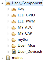
#include "User_Component/User_Mcu/User_System.h"
#include "User_Component/LED_GPIO/LED_GPIO.h"
#include "User_Component/LED_PWM/LED_PWM.h"
#include "User_Component/MY_ADC/MY_ADC.h"
#include "User_Component/Key/Key.h"
#include "User_Component/mySci/mySci.h"
#include "User_Component/MY_CAP/MY_CAP.h"
⑧/*main.c*/
/*
* main.c
*/
#define TARGET_GLOBAL 1
#include "User_Component/User_Device.h"
#include "Application\app.h"
TARGET_EXT uint16_t NOW_CMPA;
//TARGET_EXT int NOW_PWM; //当前PWM占空比
char *msg;
char buf[10];
voidmain(void)
{
//1. configure
System_config();
LED_GPIO_config();
LED_PWM_config();
MY_ADC_config();
KEY_config();
SCI_config();
MY_CAP_config();
//
//2. initial
System_initial();
LED_GPIO_initial();
LED_PWM_initial();
MY_ADC_initial();
KEY_initial();
SCI_initial();
MY_CAP_initial();
//3. Interrupt configure and initial (if use interrupt)
LED_PWM_INT_config();
MY_ADC_INT_config();
KEY_INT_config();
MY_CAP_INT_config();
//4. the global interrupt start (if use interrupt)
SystemINT_start();
msg = "\r\n\n\n虚拟温度控制系统!\0";
scia_msg(msg);
//5. main LOOP
for( ; ; )
{
//NOW_CMPA=PWM_getCmpA(myPwm1);
//NOW_PWM=NOW_CMPA/100;
// call API from app.h
//led_control();
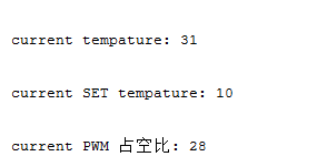
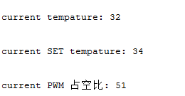
msg = "\r\n\n\n current tempature: \0";
scia_msg(msg);
buf[0] = MY_ADC/10 + 48;
buf[1] = MY_ADC%10 + 48;
buf[2] = 0;
msg = buf;
scia_msg(msg);
msg = "\r\n\n\n current SET tempature: \0";
scia_msg(msg);
buf[0] = SET_TEMP/10 + 48;
buf[1] = SET_TEMP%10 + 48;
buf[2] = 0;
msg = buf;
scia_msg(msg);
msg = "\r\n\n\n current PWM 占空比: \0";
scia_msg(msg);
buf[0] = NOW_PWM/10 + 48;
buf[1] = NOW_PWM%10 + 48;
buf[2] = 0;
msg = buf;
scia_msg(msg);
delay(2000000);
6、调试总结
首先,通过大分频从LED查看PWM模块是否正常工作。之后改变分频系数和周期实现1K Hz的PWM波。
然后,测试ADC模块。通过查看expression的变量查看温度。
测试CAP模块。通过expression查看PWM占空比是否正确。
最后测试SCI模块。将温度和占空比传送到上位机查看。
得到结果截图如下:
7、设计心得体会
通过这次课程设计,我对代码的模块化编程有了更深入的了解,通过模块化编程让整地代码的可读性有了很大的提高,也提高了编程的速度。同时也学习了通过查看芯片的手册,加深对函数的理解,例如通过看芯片手册波形,计数方式的查看令我加深对PWM,ECAP模块编程的理解。更好地理解各函数的用途。对课题的整体进行合理的布局,对CCS等软件的使用和调试也更加熟练。同时也通过与同学的交流沟通发现程序中自己没有发现的BUG,更加完善了代码。
8、参考文献
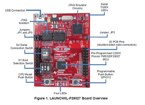
1、LAUNCHXL-F28027 C2000 Piccolo LaunchPad Experimenter Kit.pdf
2、王武,蔡逢煌.嵌入式系统技术基础与实践.福州大学电气工程与自动化学院