大学物理实验报告
Ferroelectric Control of Spin Polarization
ABSTRACT
A current drawback of spintronics is the large power that is usually required for magnetic writing, in contrast with nanoelectronics, which relies on “zero-current,” gate-controlled operations. Efforts have been made to control the spin-relaxation rate, the Curie temperature, or the magnetic anisotropy with a gate voltage, but these effects are usually small and volatile. We used ferroelectric tunnel junctions with ferromagnetic electrodes to demonstrate local, large, and nonvolatile control of carrier spin polarization by electrically switching ferroelectric polarization. Our results represent a giant type of interfacial magnetoelectric coupling and suggest a low-power approach for spin-based information control.
Controlling the spin degree of freedom by purely electrical means is currently an important challenge in spintronics (1, 2). Approaches based on spin-transfer torque (3) have proven very successful in controlling the direction of magnetization in a ferromagnetic layer, but they require the injection of high current densities. An ideal solution would rely on the application of an electric field across an insulator, as in existing nanoelectronics. Early experiments have demonstrated the volatile modulation of spin-based properties with a gate voltage applied through a dielectric. Notable examples include the gate control of the spin-orbit interaction in III-V quantum wells (4), the Curie temperature TC (5), or the magnetic anisotropy (6) in magnetic semiconductors with carrier-mediated exchange interactions; for example, (Ga,Mn)As or (In,Mn)As. Electric field–induced modifications of magnetic anisotropy at room temperature have also been reported recently in ultrathin Fe-based layers (7, 8).
A nonvolatile extension of this approach involves replacing the gate dielectric by a ferroelectric and taking advantage of the hysteretic response of its order parameter (polarization) with an electric field. When combined with (Ga,Mn)As channels, for instance, a remanent control of TC over a few kelvin was achieved through polarization-driven charge depletion/accumulation (9, 10), and the magnetic anisotropy was modified by the coupling of piezoelectricity and magnetostriction (11, 12). Indications of an electrical control of magnetization have also been provided in magnetoelectric heterostructures at room temperature (13–17).
Recently, several theoretical studies have predicted that large variations of magnetic properties may occur at interfaces between ferroelectrics and high-TC ferromagnets such as Fe (18–20), Co2MnSi (21), or Fe3O4 (22). Changing the direction of the ferroelectric polarization has been predicted to influence not only the interfacial anisotropy and magnetization, but also the spin polarization. Spin polarization [i.e., the normalized difference in the density of states (DOS) of majority and minority spin carriers at the Fermi level (EF)] is typically the key parameter controlling the response of spintronics systems, epitomized by magnetic tunnel junctions in which the tunnel magnetoresistance (TMR) is related to the electrode spin polarization by the Jullière formula (23). These predictions suggest that the nonvolatile character of ferroelectrics at the heart of ferroelectric random access memory technology (24) may be exploited in spintronics devices such as magnetic random access memories or spin field-effect transistors (2). However, the nonvolatile electrical control of spin polarization has not yet been demonstrated.
We address this issue experimentally by probing the spin polarization of electrons tunneling from an Fe electrode through ultrathin ferroelectric BaTiO3 (BTO) tunnel barriers (Fig. 1A). The BTO polarization can be electrically switched to point toward or away from the Fe electrode. We used a half-metallic La0.67Sr0.33MnO3(LSMO) (25) bottom electrode as a spin detector in these artificial multiferroic tunnel junctions (26, 27). Magnetotransport experiments provide evidence for a large and reversible dependence of the TMR on ferroelectric polarization direction.
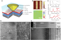
Fig. 1
(A) Sketch of the nanojunction defined by electrically controlled nanoindentation. A thin resist is spin-coated on the BTO(1 nm)/LSMO(30 nm) bilayer. The nanoindentation is performed with a conductive-tip atomic force microscope, and the resulting nano-hole is filled by sputter-depositing Au/CoO/Co/Fe. (B) (Top) PFM phase image of a BTO(1 nm)/LSMO(30 nm) bilayer after poling the BTO along 1-by-4–μm stripes with either a negative or positive (tip-LSMO) voltage. (Bottom) CTAFM image of an unpoled area of a BTO(1 nm)/LSMO(30 nm) bilayer. Ω, ohms. (C) X-ray absorption spectra collected at room temperature close to the Fe L3,2 (top), Ba M5,4 (middle), and Ti L3,2 (bottom) edges on an AlOx(1.5 nm)/Al(1.5 nm)/Fe(2 nm)/BTO(1 nm)/LSMO(30 nm)//NGO(001) heterostructure. (D) HRTEM and (E) HAADF images of the Fe/BTO interface in a Ta(5 nm)/Fe(18 nm)/BTO(50 nm)/LSMO(30 nm)//NGO(001) heterostructure. The white arrowheads in (D) indicate the lattice fringes of {011} planes in the iron layer. [110] and [001] indicate pseudotetragonal crystallographic axes of the BTO perovskite.
The tunnel junctions that we used in this study are based on BTO(1 nm)/LSMO(30 nm) bilayers grown epitaxially onto (001)-oriented NdGaO3 (NGO) single-crystal substrates (28). The large (~180°) and stable piezoresponse force microscopy (PFM) phase contrast (28) between negatively and positively poled areas (Fig. 1B, top) indicates that the ultrathin BTO films are ferroelectric at room temperature (29). The persistence of ferroelectricity for such ultrathin films of BTO arises from the large lattice mismatch with the NGO substrate (–3.2%), which is expected to dramatically enhance ferroelectric properties in this highly strained BTO (30). The local topographical and transport properties of the BTO(1 nm)/LSMO(30 nm) bilayers were characterized by conductive-tip atomic force microscopy (CTAFM) (28). The surface is very smooth with terraces separated by one-unit-cell–high steps, visible in both the topography (29) and resistance mappings (Fig. 1B, bottom). No anomalies in the CTAFM data were observed over lateral distances on the micrometer scale.
We defined tunnel junctions from these bilayers by a lithographic technique based on CTAFM (28, 31). Top electrical contacts of diameter ~10 to 30 nm can be patterned by this nanofabrication process. The subsequent sputter deposition of a 5-nm-thick Fe layer, capped by a Au(100 nm)/CoO(3.5 nm)/Co(11.5 nm) stack to increase coercivity, defined a set of nanojunctions (Fig. 1A). The same Au/CoO/Co/Fe stack was deposited on another BTO(1 nm)/LSMO(30 nm) sample for magnetic measurements. Additionally, a Ta(5 nm)/Fe(18 nm)/BTO(50 nm)/LSMO(30 nm) sample and a AlOx(1.5 nm)/Al(1.5 nm)/Fe(2 nm)/BTO(1 nm)/LSMO(30 nm) sample were realized for structural and spectroscopic characterizations.
We used both a conventional high-resolution transmission electron microscope (HRTEM) and the NION UltraSTEM 100 scanning transmission electron microscope (STEM) to investigate the Fe/BTO interface properties of the Ta/Fe/BTO/LSMO sample. The epitaxial growth of the BTO/LSMO bilayer on the NGO substrate was confirmed by HRTEM and high-resolution STEM images. The low-resolution, high-angle annular dark field (HAADF) image of the entire heterostructure shows the sharpness of the LSMO/BTO interface over the studied area (Fig. 1E, top). Figure 1D reveals a smooth interface between the BTO and the Fe layers. Whereas the BTO film is epitaxially grown on top of LSMO, the Fe layer consists of textured nanocrystallites. From the in-plane (a) and out-of-plane (c) lattice parameters in the tetragonal BTO layer, we infer that c/a = 1.016 ± 0.008, in good agreement with the value of 1.013 found with the use of x-ray diffraction (29). The interplanar distances for selected crystallites in the Fe layer [i.e., ~2.03 Å (Fig. 1D, white arrowheads)] are consistent with the {011} planes of body-centered cubic (bcc) Fe.
We investigated the BTO/Fe interface region more closely in the HAADF mode of the STEM (Fig. 1E, bottom). On the BTO side, the atomically resolved HAADF image allows the distinction of atomic columns where the perovskite A-site atoms (Ba) appear as brighter spots. Lattice fringes with the characteristic {100} interplanar distances of bcc Fe (~2.86 Å) can be distinguished on the opposite side. Subtle structural, chemical, and/or electronic modifications may be expected to occur at the interfacial boundary between the BTO perovskite-type structure and the Fe layer. These effects may lead to interdiffusion of Fe, Ba, and O atoms over less than 1 nm, or the local modification of the Fe DOS close to EF, consistent with ab initio calculations of the BTO/Fe interface (18–20).
To characterize the oxidation state of Fe, we performed x-ray absorption spectroscopy (XAS) measurements on a AlOx(1.5 nm)/Al(1.5 nm)/Fe(2 nm)/BTO(1 nm)/LSMO(30 nm) sample (28). The probe depth was at least 7 nm, as indicated by the finite XAS intensity at the La M4,5 edge (28), so that the entire Fe thickness contributed substantially to the signal. As shown in Fig. 1C (top), the spectrum at the Fe L2,3 edge corresponds to that of metallic Fe (32). The XAS spectrum obtained at the Ba M4,5 edge (Fig. 1C, middle) is similar to that reported for Ba2+ in (33). Despite the poor signal-to-noise ratio, the Ti L2,3 edge spectrum (Fig. C, bottom) shows the typical signature expected for a valence close to 4+ (34). From the XAS, HRTEM, and STEM analyses, we conclude that the Fe/BTO interface is smooth with no detectable oxidation of the Fe layer within a limit of less than 1 nm.
After cooling in a magnetic field of 5 kOe aligned along the [110] easy axis of pseudocubic LSMO (which is parallel to the orthorhombic [100] axis of NGO), we characterized the transport properties of the junctions at low temperature (4.2 K). Figure 2A (middle) shows a typical resistance–versus–magnetic field R(H) cycle recorded at a bias voltage of –2 mV (positive bias corresponds to electrons tunneling from Fe to LSMO). The bottom panel of Fig. 2A shows the magnetic hysteresis loop m(H) of a similar unpatterned sample measured with superconducting quantum interference device (SQUID) magnetometry. When we decreased the magnetic field from a large positive value, the resistance dropped in the –50 to –250 Oe range and then followed a plateau down to –800 Oe, after which it sharply returned to the high-resistance state. We observed a similar response when cycling the field back to large positive values. A comparison with the m(H) loop indicates that the switching fields in R(H) correspond to changes in the relative magnetic configuration of the LSMO and Fe electrodes from parallel (at high field) to antiparallel (at low field). The magnetically softer LSMO layer switched at lower fields (50 to 250 Oe) compared with the Fe layer, for which coupling to the exchange-biased Co/CoO induces larger and asymmetric coercive fields (–800 Oe, 300 Oe). The observed R(H) corresponds to a negative TMR = (Rap –Rp)/Rap of –17% [Rp and Rap are the resistance in the parallel (p) and antiparallel (ap) magnetic configurations, respectively; see the sketches in Fig. 2A]. Within the simple Jullière model of TMR (23) and considering the large positive spin polarization of half-metallic LSMO (25), this negative TMR corresponds to a negative spin polarization for bcc Fe at the interface with BTO, in agreement with ab initio calculations (18–20).

Fig. 2
(A) (Top) Device schematic with black arrows to indicate magnetizations. p, parallel; ap, antiparallel. (Middle) R(H) recorded at –2 mV and 4.2 K showing negative TMR. (Bottom) m(H) recorded at 30 K with a SQUID magnetometer. emu, electromagnetic units. (B) (Top) Device schematic with arrows to indicate ferroelectric polarization. (Bottom) I(VDC) curves recorded at 4.2 K after poling the ferroelectric down (orange curve) or up (brown curve). The bias dependence of the TER is shown in the inset.
As predicted (35–38) and demonstrated (29) previously, the tunnel current across a ferroelectric barrier depends on the direction of the ferroelectric polarization. We also observed this effect in our Fe/BTO/LSMO junctions. As can be seen in Fig. 2B, after poling the BTO at 4.2 K to orient its polarization toward LSMO or Fe (with a poling voltage of VP– ≈ –1 V or VP+ ≈ 1 V, respectively; see Fig. 2B sketches), current-versus-voltage I(VDC) curves collected at low bias voltages showed a finite difference corresponding to a tunnel electroresistance as large asTER = (IVP+ – IVP–)/IVP– ≈ 37% (Fig. 2B, inset). This TER can be interpreted within an electrostatic model (36–39), taking into account the asymmetric deformation of the barrier potential profile that is created by the incomplete screening of polarization charges by different Thomas-Fermi screening lengths at Fe/BTO and LSMO/BTO interfaces. Piezoelectric-related TER effects (35, 38) can be neglected as the piezoelectric coefficient estimated from PFM experiments is too small in our clamped films (29). TER measurements performed on a BTO(1 nm)/LSMO(30 nm) bilayer with the use of a CTAFM boron-doped diamond tip as the top electrode showed values of ~200% (29). Given the strong sensitivity of the TER on barrier parameters and barrier-electrode interfaces, these two values are not expected to match precisely. We anticipate that the TERvariation between Fe/BTO/LSMO junctions and CTAFM-based measurements is primarily the result of different electrostatic boundary conditions.
Switching the ferroelectric polarization of a tunnel barrier with voltage pulses is also expected to affect the spin-dependent DOS of electrodes at a ferromagnet/ferroelectric interface. Interfacial modifications of the spin-dependent DOS of the half-metallic LSMO by the ferroelectric BTO are not likely, as no states are present for the minority spins up to ~350 meV above EF (40, 41). For 3d ferromagnets such as Fe, large modifications of the spin-dependent DOS are expected, as charge transfer between spin-polarized empty and filled states is possible. For the Fe/BTO interface, large changes have been predicted through ab initio calculations of 3d electronic states of bcc Fe at the interface with BTO by several groups (18–20).
To experimentally probe possible changes in the spin polarization of the Fe/BTO interface, we measured R(H) at a fixed bias voltage of –50 mV after aligning the ferroelectric polarization of BTO toward Fe or LSMO. R(H) cycles were collected for each direction of the ferroelectric polarization for two typical tunnel junctions of the same sample (Fig. 3, B and C, for junction #1; Fig. 3, D and E, for junction #2). In both junctions at the saturating magnetic field, high- and low-resistance states are observed when the ferroelectric polarization points toward LSMO or Fe, respectively, with a variation of ~ 25%. This result confirms the TER observations in Fig. 2B.

Fig. 3
(A) Sketch of the electrical control of spin polarization at the Fe/BTO interface. (B and C) R(H) curves for junction #1 (VDC = –50 mV, T = 4.2 K) after poling the ferroelectric barrier down or up, respectively. (Dand E) R(H) curves for junction #2 (VDC = –50 mV, T= 4.2 K) after poling the ferroelectric barrier down or up, respectively.
More interestingly, here, the TMR is dramatically modified by the reversal of BTO polarization. For junction #1, the TMR amplitude changes from –17 to –3% when the ferroelectric polarization is aligned toward Fe or LSMO, respectively (Fig. 3, B and C). Similarly for junction #2, the TMR changes from –45 to –19%. Similar results were obtained on Fe/BTO (1.2 nm)/LSMO junctions (28). Within the Jullière model (23), these changes in TMRcorrespond to a large (or small) spin polarization at the Fe/BTO interface when the ferroelectric polarization of BTO points toward (or away from) the Fe electrode. These experimental data support our interpretation regarding the electrical manipulation of the spin polarization of the Fe/BTO interface by switching the ferroelectric polarization of the tunnel barrier.
To quantify the sensitivity of the TMR with the ferroelectric polarization, we define a term, the tunnel electromagnetoresistance, as TEMR = (TMRVP+ – TMRVP–)/TMRVP–. Large values for the TEMR are found for junctions #1 (450%) and #2 (140%), respectively. This electrical control of the TMR with the ferroelectric polarization is repeatable, as shown in Fig. 4 for junction #1 where TMR curves are recorded after poling the ferroelectric up, down, up, and down, sequentially (28).

Fig. 4
TMR(H) curves recorded for junction #1 (VDC = –50 mV, T = 4.2 K) after poling the ferroelectric up (VP+), down (VP–), up (VP+), and down (VP–).
For tunnel junctions with a ferroelectric barrier and dissimilar ferromagnetic electrodes, we have reported the influence of the electrically controlled ferroelectric barrier polarization on the tunnel-current spin polarization. This electrical influence over magnetic degrees of freedom represents a new and interfacial magnetoelectric effect that is large because spin-dependent tunneling is very sensitive to interfacial details. Ferroelectrics can provide a local, reversible, nonvolatile, and potentially low-power means of electrically addressing spintronics devices.
Supporting Online Material
www.sciencemag.org/cgi/content/full/science.1184028/DC1
Materials and Methods
Figs. S1 to S5
References
· Received for publication 30 October 2009.
· Accepted for publication 4 January 2010.
References and Notes
1. C. Chappert, A. Fert, F. N. Van Dau, The emergence of spin electronics in data storage. Nat. Mater. 6,813 (2007).
2. I. ?uti?, J. Fabian, S. Das Sarma, Spintronics: Fundamentals and applications. Rev. Mod. Phys. 76,323 (2004).
3. J. C. Slonczewski, Current-driven excitation of magnetic multilayers. J. Magn. Magn. Mater. 159, L1(1996).
4. J. Nitta, T. Akazaki, H. Takayanagi, T. Enoki
, Gate control of spin-orbit interaction in an inverted In0.53Ga0.47As/In0.52Al0.48As heterostructure. Phys. Rev. Lett. 78, 1335 (1997).
5. H. Ohno et al., Electric-field control of ferromagnetism. Nature 408, 944 (2000).
6. D. Chiba et al., Magnetization vector manipulation by electric fields. Nature 455, 515 (2008).
7. M. Weisheit et al., Electric field–induced modification of magnetism in thin-film ferromagnets. Science315, 349 (2007).
8. T. Maruyama et al., Large voltage-induced magnetic anisotropy change in a few atomic layers of iron.Nat. Nanotechnol. 4, 158 2009).
9. S. W. E. Riester et al., Toward a low-voltage multiferroic transistor: Magnetic (Ga,Mn)As under ferroelectric control. Appl. Phys. Lett. 94, 063504 (2009).
10. I. Stolichnov et al., Non-volatile ferroelectric control of ferromagnetism in (Ga,Mn)As. Nat. Mater. 7, 464(2008).
11. C. Bihler et al., Ga1?xMnxAs/piezoelectric actuator hybrids: A model system for magnetoelastic magnetization manipulation. Phys. Rev. B 78, 045203 (2008).
12. M. Overby, A. Chernyshov, L. P. Rokhinson, X. Liu, J. K. Furdyna
, GaMnAs-based hybrid multiferroic memory device. Appl. Phys. Lett. 92, 192501 (2008).
13. C. Thiele, K. Dörr, O. Bilani, J. Rödel, L. Schultz, Influence of strain on the magnetization and magnetoelectric effect in La0.7A0.3MnO3∕PMN-PT(001)(A=Sr,Ca). Phys.Rev.B 75, 054408 (2007).
14. W. Eerenstein, M. Wiora, J. L. Prieto, J. F. Scott, N. D. Mathur, Giant sharp and persistent converse magnetoelectric effects in multiferroic epitaxial heterostructures. Nat. Mater. 6, 348 (2007).
15. T. Kanki, H. Tanaka, T. Kawai, Electric control of room temperature ferromagnetism in a Pb(Zr0.2Ti0.8)O3/La0.85Ba0.15MnO3 field-effect transistor. Appl. Phys. Lett. 89, 242506 (2006).
16. Y.-H. Chu et al., Electric-field control of local ferromagnetism using a magnetoelectric multiferroic. Nat. Mater. 7, 478 2008).
17. S. Sahoo et al., Ferroelectric control of magnetism in BaTiO3∕Fe heterostructures via interface strain coupling. Phys. Rev. B 76, 092108 (2007).
18. C.-G. Duan, S. S. Jaswal, E. Y. Tsymbal, Predicted magnetoelectric effect in Fe/BaTiO3 multilayers: Ferroelectric control of magnetism. Phys. Rev. Lett. 97, 047201 (2006).
19. M. Fechner et al., Magnetic phase transition in two-phase multiferroics predicted from first principles.Phys. Rev. B 78, 212406 (2008).
20. J. Lee, N. Sai, T. Cai, Q. Niu, A. A. Demkov, preprint available at http://arxiv.org/abs/0912.3492v1.
21. K. Yamauchi, B. Sanyal, S. Picozzi, Interface effects at a half-metal/ferroelectric junction. Appl. Phys. Lett. 91, 062506 (2007).
22. M. K. Niranjan, J. P. Velev, C.-G. Duan, S. S. Jaswal, E. Y. Tsymbal
, Magnetoelectric effect at the Fe3O4/BaTiO3 (001) interface: A first-principles study. Phys. Rev. B 78, 104405 (2008).
23. M. Jullière, Tunneling between ferromagnetic films. Phys. Lett. A 54, 225 (1975).
24. J. F. Scott
, Applications of modern ferroelectrics. Science 315, 954 (2007).
25. M. Bowen et al., Nearly total spin polarization in La2/3Sr1/3MnO3 from tunneling experiments. Appl. Phys. Lett. 82, 233 (2003).
26. J. P. Velev et al., Magnetic tunnel junctions with ferroelectric barriers: Prediction of four resistance states from first principles. Nano Lett. 9, 427 (2009).
27. F. Yang et al., Eight logic states of tunneling magnetoelectroresistance in multiferroic tunnel junctions.J. Appl. Phys. 102, 044504 (2007).
28. Materials and methods are available as supporting material on Science Online.
29. V. Garcia et al., Giant tunnel electroresistance for non-destructive readout of ferroelectric states. Nature460, 81 (2009).
30. K. J. Choi et al., Enhancement of ferroelectricity in strained BaTiO3 thin films. Science 306, 1005(2004).
31. K. Bouzehouane et al., Nanolithography based on real-time electrically controlled indentation with an atomic force microscope for nanocontact elaboration. Nano Lett. 3, 1599 (2003).
32. T. J. Regan et al., Chemical effects at metal/oxide interfaces studied by x-ray-absorption spectroscopy.Phys. Rev. B 64, 214422 (2001).
33. N. Hollmann et al., Electronic and magnetic properties of the kagome systems YBaCo4O7 and YBaCo3MO7 (M=Al, Fe). Phys. Rev. B 80, 085111 (2009).
34. M. Abbate et al., Soft-x-ray-absorption studies of the location of extra charges induced by substitution in controlled-valence materials. Phys. Rev. B 44, 5419 (1991).
35. E. Y. Tsymbal, H. Kohlstedt, Tunneling across a ferroelectric. Science 313, 181 (2006).
36. M. Ye. Zhuravlev, R. F. Sabirianov, S. S. Jaswal, E. Y. Tsymbal, Giant electroresistance in ferroelectric tunnel junctions. Phys. Rev. Lett. 94, 246802 (2005).
37. M. Ye. Zhuravlev, R. F. Sabirianov, S. S. Jaswal, E. Y. Tsymbal, Erratum: Giant electroresistance in ferroelectric tunnel junctions. Phys. Rev. Lett. 102, 169901 2009).
38. H. Kohlstedt, N. A. Pertsev, J. Rodriguez Contreras, R. Waser, Theoretical current-voltage characteristics of ferroelectric tunnel junctions. Phys. Rev. B 72, 125341 (2005).
39. M. Gajek et al., Tunnel junctions with multiferroic barriers. Nat. Mater. 6, 296 (2007).
40. M. Bowen et al., Spin-polarized tunneling spectroscopy in tunnel junctions with half-metallic electrodes.Phys. Rev. Lett. 95, 137203 (2005).
41. J. D. Burton, E. Y. Tsymbal, Prediction of electrically induced magnetic reconstruction at the manganite/ferroelectric interface. Phys. Rev. B 80, 174406 (2009).
42. We thank R. Guillemet, C. Israel, M. E. Vickers, R. Mattana, J.-M. George, and P. Seneor for technical assistance, and C. Colliex for fruitful discussions on the microscopy measurements. This study was partially supported by the France-U.K. Partenariat Hubert Curien Alliance program, the French Réseau Thématique de Recherche Avancée Triangle de la Physique, the European Union (EU) Specific Targeted Research Project (STRep) Manipulating the Coupling in Multiferroic Films, EU STReP Controlling Mesoscopic Phase Separation, U.K. Engineering and Physical Sciences Research Council grant EP/E026206/I, French C-Nano Île de France, French Agence Nationale de la Recherche (ANR) Oxitronics, French ANR Alicante, the European Enabling Science and Technology through European Elelctron Microscopy program, and the French Microscopie Electronique et Sonde Atomique network. X.M.
acknowledges support from Comissionat per a Universitats i Recerca (Generalitat de Catalunya).