EDA�ϻ�ʵ�鱨��
�༶��021211
������������
ѧ�ţ�02121056
ʵ��һ��QUARTUS II����ʹ�ü���ϵ�·��Ʒ���
ʵ��Ŀ�ģ�
ѧϰQUARTUS II������ʹ�ã������������̵Ľ�����VHDLԴ�ļ�����ƺͲ��η���Ȼ������ݣ�
ʵ�����ݣ�
1. ��ѡһ��·ѡ���������
1.1ʵ������
��������Quartus�����4ѡ1��·ѡ�������ı��༭����ͷ�����ԵȲ��裬�������沨�Ρ�
���裺
��1�� �����������ļ��кͱ༭����ļ���
��2�� �������̣�
��3�� ����ǰ���ã�
��4�� ȫ�̱��룻
��5�� ʱ����档
1.2������ƣ�
library ieee;
use ieee.std_logic_1164.all;
entity mux41 is
port
(
s:IN STD_LOGIC_VECTOR(1 DOWNTO 0);
a,b,c,d:IN STD_LOGIC;
y : out std_logic
);
end mux41;
architecture behavior of mux41 is
begin
process(s)
begin
IF s="00" THEN
y<=a;
ELSIF s="01" THEN
y<=b;
ELSIF s="10" THEN
y<=c;
ELSIF s="11" THEN
y<=d;
END IF;
END PROCESS;
END BEHAVIOR;
1.3���沨��
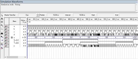
ͼ ��ѡһ��·ѡ�������η�����
1.4�������
ͨ����ʵ�������о������Է��ָó���ɹ�ʵ����4ѡ1��·ѡ�����Ĺ��ܡ���s=00ʱ��y=a��s=01ʱ��y=b��s=10ʱ��y=c��s=11ʱ��y=d.��ȫʵ����4ѡ1��·ѡ�����Ĺ��ܡ�
2. �߶�������������Ʒ���
2��1 ʵ��ԭ����
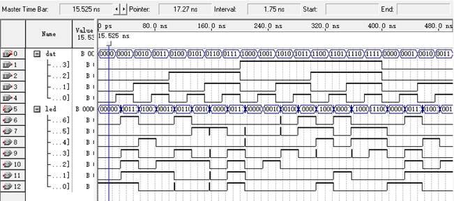
7�������Ǵ���ϵ�·��ͨ����С��ģר��IC����74��4000ϵ�е�����ֻ����ʮ����BCD�����룬Ȼ������ϵͳ�е����ݴ��������㶼��2���Ƶģ�����������ﶼ��16���Ƶģ�Ϊ������16��������������ʾ�����ķ�����������VHDL���������FPGA��CPLD��ʵ�֡�����ʵ�������ʵ����һĿ�ġ���1��Ϊ7��BCD������������ƣ�����ź�LED7S��7λ�ֱ����ʵ��ͼ1����ܵ�7���Σ���λ����λ���ҡ����統LED7S���Ϊ "0010010" ʱ������ܵ�7���Σ�g��f��e��d��c��b��a�ֱ��0��0��1��0��0��1��0��ʵ���е������Ϊ�������ģ����е͵�ƽ�Ķη����������������ʾ��5����

2��2 ʵ�����ݣ�
�ο�������߶�������������QUARTUS II�϶����³�����б༭�����롢�ۺϡ����䡢���棬�����������źŵ�ʱ����沨�Ρ�
2��3 ������ƣ�
library ieee;
use ieee.std_logic_1164.all;
entity mu7 is
port( dat:in std_logic_vector(3 downto 0);
led:out std_logic_vector(6 downto 0));
end mu7;
architecture behave of mu7 is
signal tmp:std_logic_vector(6 downto 0);
begin
process(dat)
begin
case dat is
when "0000"=>tmp<="0000001";
when "0001"=>tmp<="1001111";
when "0010"=>tmp<="0010010";
when "0011"=>tmp<="0000110";
when "0100"=>tmp<="1001100";
when "0101"=>tmp<="0100100";
when "0110"=>tmp<="0100000";
when "0111"=>tmp<="0001111";
when "1000"=>tmp<="0000000";
when "1001"=>tmp<="0000100";
when "1010"=>tmp<="0001000";
when "1011"=>tmp<="1100000";
when "1100"=>tmp<="0110001";
when "1101"=>tmp<="1000010";
when "1110"=>tmp<="0110000";
when "1111"=>tmp<="0111000";
when others=>null;
end case;
end process;
led<=tmp;
end behave;
2��4���沨�Σ�
2��5���������
ͨ�����η��棬�õ��ó���ɹ�ʵ�����߶��������Ĺ��ܣ�����datΪ��λ��������������ˣ�ledΪ�߶�������������ˡ�
ʵ��� �������������ʾ
ʵ��Ŀ�ģ�
��1����Ϥ����QUARTUS II�е�ԭ��ͼ���뷨�����ϵ�·�����ղ�λ���Ƶķ���;
��2��ѧϰ��������ơ�������Ʒ����������������뷽ʽ�ķ��棬�����е�·��������ʾ��֤��
ʵ�����ݣ�
1�� ��ɼ��������
1��1ʵ�����ݣ�
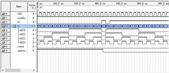
��ƺ����첽����ͼ���ʹ�ܵ�4λ�����ƼӼ��ɿؼ�������
1��2������ƣ�
library ieee;
use ieee.std_logic_1164.all;
use ieee.std_logic_unsigned.all;
ENTITY cnt4 IS
PORT ( CLK ,enable,updown,reset: in std_logic ;
Oc:out std_logic;
Q : BUFFER INTEGER range 15 downto 0 ) ;
END ENTITY cnt4 ;
ARCHITECTURE bhv OF cnt4 IS
BEGIN
PROCESS (CLK,reset,enable,updown)
BEGIN
if reset='1' then
Q<=0;
else
if enable='1' then
IF CLK'EVENT AND CLK = '1' THEN
if updown='1'then
Q <= Q + 1 ;
else
Q<=Q-1;
end if;
if Q=15 then
Oc<='1';
end if;
if Q=0 then
Oc<='0';
end if;
END IF;
end if;
end if;
END PROCESS;
END bhv;
1��3���沨�Σ�
1��4���������
ͨ�����η��棬�ɵøó������ʵ��4λ�����ƼӼ��ɿؼ������Ĺ��ܡ����п���enable����ʹ��������ͣ���������������reset����ʹ��������λ��updown���Կ��Ƽ������ǡ��ӡ����ǡ����������Կ���Q����η�������гɹ���0�ӵ�15���ִ�15����0���ɼ�ʵ�����dzɹ��ġ�
2�� ��������ʾ�������������
2��1ʵ�����ݣ�
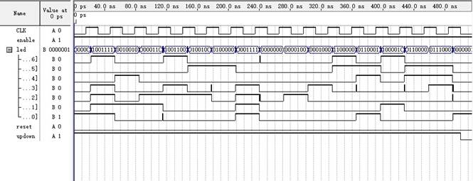
��ԭ��ͼ���뷨��ʵ��ͼ2�ķ�ʽ����ǰ����Ƶ��߶�������DecL7S�ͼ�����Ϊ�ײ�Ԫ������ɡ���������ʾ���롱�Ķ����ļ���ơ�
2��2������ƣ�
����ģ��Ĵ�����֮ǰ��Ƶ�ʵ�����һ�£�ֻ��50M��Ƶ���Ĵ�����Ҫ�������
50M��Ƶ���������£�
library ieee;
use ieee.std_logic_1164.all;
use ieee.std_logic_unsigned.all;
ENTITY cnt50 IS
PORT ( CLK ,enable,updown,reset: in std_logic ;
Oc:out std_logic;
Q : BUFFER INTEGER range 49999999 downto 0 );
END ENTITY cnt50;
ARCHITECTURE bhv OF cnt50 IS
BEGIN
PROCESS (CLK,reset,updown,enable)
BEGIN
if reset='1' then
Q<=0;
else
if enable='1' then
IF CLK'EVENT AND CLK = '1' THEN
if updown='1'then
Q <= Q + 1 ;
else
Q<=Q-1;
end if;
if Q=49999999 then
Oc<='1';
end if;
if Q=0 then
Oc<='0';
end if;
END IF;
end if;
end if;
END PROCESS;
END bhv;
2��3���η��棺
2��4��ģ�����ӵ�·ԭ��ͼ��

ʵ��ͼ2 �����������������ӵ�·�Ķ����ļ�ԭ��ͼ
2��5���������
����ʵ������֪����ģ��Ĺ��ܶ��ܳɹ�ʵ�֣�����enable����ʹ��������ͣ���������������reset����ʹ��������λ��updown���Կ��Ƽ������ǡ��ӡ����ǡ����������߶�������������������ͨ���������ʾ�������ɹ�ʵ���˼�������ʾ�������ơ�
ʵ��3������ҵ��� ��2��������
(һ) �������Ҫ��
���һ��2����������Ҫ�����£�
1. ������������Ϊ��Ч���÷����������ʾ�Ƿ��������ȴ���Ȩ��
2. ÿ��2λ�Ʒ���ʾ������˲��ӷ֣�����˿ɼ�10�֡�20�֡�30�֣�
3. ÿ��������а���λ����������������һ�⣻
4. �ۼƼӷֿ��ɲ�����ʱ�����
(��) ��������ͼ��

(��) �����ܣ�
1. �˳�����Ҫ����������ɣ������𡢼ӷ֡���ʾ��
2. ��һ���������ȴ���Ȩ�����������������һ���ٰ�����Ч������������а���λ���������ٴ�����
3. ÿ����2���������ʾ�ۼӼƷ������������Ϊ3�����ð�������������ܵ�ĩλʼ����ʾ0.
(��) �������:
ʵ�壺
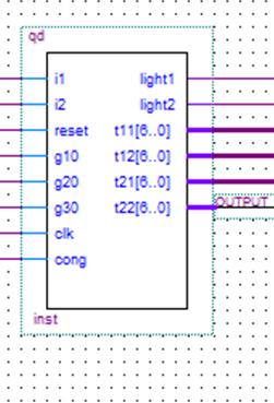 ��ʵ������ͼ��
����������룺
entity qd is
port(i1,i2 : in bit;
reset : in bit;
g10,g20,g30:in bit; --�ӷ�
light1,light2:out bit:='0'; --�����־��
t11:out std_logic_vector(6 downto 0):= "1000000"; --��һ�˷�����ʮλ����λ��
t12:out std_logic_vector(6 downto 0):= "1000000";
t21:out std_logic_vector(6 downto 0):= "1000000"; --�ڶ��˷�����ʮλ����λ��
t22:out std_logic_vector(6 downto 0):= "1000000";
clk:in bit; --ʱ��
cong:in bit --����
);
end qd;
architecture stru of qd is
signal cs1:integer range 0 to 9;
signal cs2:integer range 0 to 9;
signal a,b:bit:='0';
signal l1,l2:bit:='0';
begin
process(clk)
begin
if clk'event and clk='1' then
if(cong='1') then
if(reset='1') then
if (i1 ='0' and a='0') then l1<='1'; a<= '1' ; --����
elsif ( i2 ='0' and a='0') then l2<='1'; a<= '1' ;
end if;
if (g10 ='0' and l1='1' and b='0' ) then cs1<=cs1+1 ; b<='1' ;
elsif (g20 ='0' and l1='1' and b='0' ) then cs1<=cs1+2 ; b<='1' ;
elsif (g30 ='0' and l1='1' and b='0' ) then cs1<=cs1+3 ; b<='1' ;
end if; --��ɵ�һ�˵ļӷ֡}
if(g10='0' and l2='1' and b='0') then cs2<=cs2+1;b<='1';
elsif(g20='0' and l2='1' and b='0') then cs2<=cs2+2;b<='1';
elsif(g30='0' and l2='1' and b='0') then cs2<=cs2+3;b<='1';
end if; --��ɵڶ��˵ļӷ֡�
if (cs1=0) then t11<="1000000"; --�������ʾ��
elsif (cs1=1) then t11<= "1111001";
elsif (cs1=2) then t11<= "0100100";
elsif (cs1=3) then t11<= "0110000";
elsif (cs1=4) then t11<= "0011001";
elsif (cs1=5) then t11<= "0010010";
elsif (cs1=6) then t11<= "0000010";
elsif (cs1=7) then t11<= "1111000";
elsif (cs1=8) then t11<= "0000000";
elsif (cs1=9) then t11<= "0010000";
else t11<= "0010000";
end if;
if (cs2=0) then t21<= "1000000" ;
elsif (cs2=1) then t21<= "1111001" ;
elsif (cs2=2) then t21<= "0100100" ;
elsif (cs2=3) then t21<= "0110000" ;
elsif (cs2=4) then t21<= "0011001" ;
elsif (cs2=5) then t21<= "0010010" ;
elsif (cs2=6) then t21<= "0000010" ;
elsif (cs2=7) then t21<= "1111000" ;
elsif (cs2=8) then t21<= "0000000" ;
elsif (cs2=9) then t21<= "0010000" ;
else t11<= "0010000";
end if;
else l1<='0';l2<='0';a<='0';b<='0';
end if;
else l1<='0';l2<='0';a<='0';b<='0';
cs1<=0 ; cs2<=0 ;
l1<='0' ; l2<='0' ;
end if;
light1<=l1;
light2<=l2;
t12<="1000000";
t22<="1000000";
end if;
end process;
end stru;
����˵����
���ݳ������Ҫ��ģ����Ҫ����3���ֹ��ܣ������𡢼ӷ֡���ʾ�������ֵ�ʵ�����£�
a) ����
������Ҫ��i1��i2��������˿��ƣ��书�ܾ���Ϊ����i1����i2�е�һ�����ź�����ʱ��������Ӧ�������־�ƾͽ����𣬴�ʱ��һ���ٰ�����Ч�����ʱ��Ϊ������ɹ���
��ش���Ϊ��
if (i1 ='0' and a='0') then l1<='1'; a<= '1' ;
elsif ( i2 ='0' and a='0') then l2<='1'; a<= '1' ;
end if;
light1<=l1;
light2<=l2;
����aΪ���ƽ�ʹ����һ������ɹ��ı�־�źţ���ʼΪ0������ɹ����ͻ��Ϊ1����ʱ������ִ�������й����ֵĴ��롣��light1��light2Ϊ1ʱ������Ӧ�������־�ƽ�����
a) �ӷֲ���
�ӷֲ��������������g10��g20��g30���ƣ��ֱ������10�֡�20�֡�30�֡���ijλѡ������ɹ�ʱ��ͨ����3������˿���Ϊ��λѡ�ּӷ֡�
�ӷֲ��ֵĴ���Ϊ��
if (g10 ='0' and l1='1' and b='0' ) then cs1<=cs1+1 ; b<='1' ;
elsif (g20 ='0' and l1='1' and b='0' ) then cs1<=cs1+2 ; b<='1' ;
elsif (g30 ='0' and l1='1' and b='0' ) then cs1<=cs1+3 ; b<='1' ;
end if;
if(g10='0' and l2='1' and b='0') then cs2<=cs2+1;b<='1';
elsif(g20='0' and l2='1' and b='0') then cs2<=cs2+2;b<='1';
elsif(g30='0' and l2='1' and b='0') then cs2<=cs2+3;b<='1';
end if;
���ڵ�ÿ��ijλѡ������ɹ���ֻ�ܽ���һ�μӷ֣������b�����ƣ�ÿ�μӷ���ɺ�b��Ϊ1����ʱ������ִ���κ���ӷ��йصĴ��룬cs1��cs2��ֵ�ֱ������λѡ�ַ�����ʮλ��ֵ��
b) ��ʾ����
��������Ҫ���߶����������ʾ��λѡ�ֵķ�������Ƶij���������£�
if (cs1=0) then t11<="1000000";
elsif (cs1=1) then t11<= "1111001";
elsif (cs1=2) then t11<= "0100100";
elsif (cs1=3) then t11<= "0110000";
elsif (cs1=4) then t11<= "0011001";
elsif (cs1=5) then t11<= "0010010";
elsif (cs1=6) then t11<= "0000010";
elsif (cs1=7) then t11<= "1111000";
elsif (cs1=8) then t11<= "0000000";
elsif (cs1=9) then t11<= "0010000";
else t11<= "0010000";
end if;
if (cs2=0) then t21<= "1000000" ;
elsif (cs2=1) then t21<= "1111001" ;
elsif (cs2=2) then t21<= "0100100" ;
elsif (cs2=3) then t21<= "0110000" ;
elsif (cs2=4) then t21<= "0011001" ;
elsif (cs2=5) then t21<= "0010010" ;
elsif (cs2=6) then t21<= "0000010" ;
elsif (cs2=7) then t21<= "1111000" ;
elsif (cs2=8) then t21<= "0000000" ;
elsif (cs2=9) then t21<= "0010000" ;
else t11<= "0010000";
end if;
��λѡ��ͨ��ǰ������ͼӷ������ֽ��ı�cs1��cs2����ֵ��������ֵ�IJ�ͬ��������λѡ��ʮλ��ֵ�������t11��t21����ʾ0~9�е�ij��������λt12��t22��ʼ����ʾΪ0��
c) ��������
�ó�����clk��cong��reset��3������ˣ�����clkΪʱ������ˣ�ͨ��ʱ�������صĵ�������ģ��ʵ�ֹ��ܡ�cong���ɲ��п��ƣ�ͨ���������˿��Խ�����ͼӷ��������ֵĿ��ƶ˳�ʼ����������ı���λѡ�ִ�ʱ�ķ�����ÿ��Ҫ������һ������ʱ����Ҫʹ���������ˡ�reset�����ʹ��������������Ϊ��ʼ״̬��
d) ��������

(��) ���η��棺
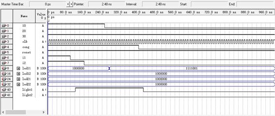
ͼʾΪi1����ɹ�����10�ֵIJ��η��档i1����ɹ���,�����־��light1���𣬲���i2��������κ������в���g10��led11��ʾΪ1������ʮ�֡��ٲ���cong�������־�Ʋ���������ʱ���Խ�����һ������ͼӷ֡�
(��) ���������
����ʵ������֪��2���������Ĺ����Ѿ����Ժܺõ�ʵ�֡���Ȼ��ʵ���������������ԭ�������һЩ���⣬���Ƕ���һһ�Ų飬��������ʵ��Ҳʹ�Ҷ�VHDL���Ժ�Quartus��ʹ�����˱Ƚ���̵��˽⡣