Measuring reflection coefficient of underwater acoustic materials with the vector hydrophone
Xiaoer Wang[1],Xiaoming Zhou2,Dawei Zhang3
Abstract. Reflection coefficient of underwater materials can be calculate by measuring impedance above the sample. some techniques which measure reflection coefficient are based on the sound pressure. This paper introduces a method for measuring reflection coefficient with vector hydrophone which can measure the instantaneous sound pressure and sound particle velocity. Then the reflection coefficient can be calculated by impedance which is acquired by sound pressure and particle velocity. Some simulations and experiments in this paper show that the method with vector hydrophone have a good performance in measuring reflection coefficient, the minimum error is 0.006. It prove that the method is effective both in vertical and oblique incidence, handy in practice.
Keywords:vector hydrophone; reflection coefficient; impedance;oblique incidence
1 Introduction
Reflection coefficient is used to guidance to applying underwater acoustic materials, and measuring reflection coefficient is a basic technology in underwater acoustic engineering. Free field method and Impedance tube method are main method of measuring reflection coefficient presently [1], the standing wave tube method has become the national standard [2].But the sample of standing wave tube could be only small one, it isn’t suit for measuring the materials which has lateral variations. Free field methods not only measure the bigger sample which has lateral variations, but also measure for oblique incidences, which inducing many interested.
The vector hydrophone consists of pressure sensors and particle velocity sensors[3], which measures pressure and orthogonal components of particle velocity co-locates and instantaneously. Many researchers are interested in it because it brings new ideas to solve the underwater acoustic problems.
This paper is focused on measuring the reflection coefficient of underwater acoustic materials with vector hydrophone. It shows a method called the surface impedance method [4], the method is briefly described in following; And for testing the method some simulations and experiments have been done.
2 The principle of surface impedance method
The mirror source model is introduced to illuminate the method [5]. In figure 1[6], A vector hydrophone is placed at a distance to the measured materials, and the y-axis of the velocity axis perpendicular to materials. The incidence sound from a point source in space (r,h),then a mirror source is placed behind the sample. then a mirror source is placed behind the sample at the distance same with the distance from point source to the sample.
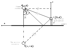
Fig. 1 the model of the surface impedance method
Where r1 is the direct propagation path, r2 is the propagation path from virtual source, which can be equivalent to the reflected wave propagation distance.
As shown in figure 1,the received pressure and y-axis particle velocity can be presented[7]:
 (1)
(1)
 (2)
(2)
Then get the normal acoustic impedance ratio according to (1) and (2):
 (3)
(3)
The reflection coefficient R can be calculated as follows:
 (4)
(4)
It shows that the normal acoustic impedance ratio is the key factory to calculate the reflection coefficient, which can be measured by vector hydrophone quickly.
In order to calculate the acoustic impedance, more accuracy result can be obtained by solving the signal from power spectrum and cross-power spectrum, which enhance the SNR.
 (5)
(5)
All above, the surface impedance method is similar to the two-hydrophone method which measures the normal acoustic impedance ratio with two pressure hydrophone [8] and the surface impedance method is handy for measuring, the vector hydrophone can enhance the SNR because it can eliminate isotropic noise.
3 Comparing the Surface Impedance Method With Two-pressure Senors
In this part,it shows some simulations. The point source is 2.2m away from material, and the vector hydrophone distant to the material is 0.25m, the incidence angle is 0°、30°, the middle point of two-pressure hydrophone is 0.25m apart from material, the distance between two-pressure hydrophone is 0.03m,the SNR is 0dB,the frequency range from 500Hz to 10kHz.

Fig. 2 compare the surface impedance method(△) with the Two-pressure senors (*) at 0º(theoretical value (■)
In figure 2 and figure 3, the measured reflection coefficient is displayed. The result of two-hydrophone is demonstrated by *,and △ represent the measured result of surface impedance method. It can be found the surface impedance method has more precise result clearly, even as oblique incidence, it has better performance.
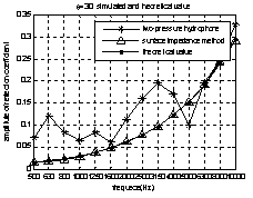
Fig. 3compare the surface impedance method (△) with the Two-pressure senors(*) at 30º(theoretical value (■)
4 Experiment Stuying
The measurement described as figure 3.the system is composed by emitting system and incepting system. Measurements are carried out in an anechoic pool .
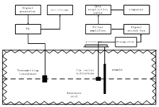
Fig. 4 the map of experiment collocation
4.1The Vector Hydropone Calibration
The vector hydrophone should be calibrated before measurement; the frequency response is shown in figure 5.
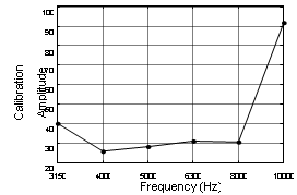
Fig. 5 the magnitude calibration functio
4.2Measurment
The measured sample is a 1m×1m×0.006m aluminum, the source is 1.9m apart from the sample, frequency range from 3.15 kHz~10 kHz, incidence angle from 0º~ 25 º .the distances between vector hydrophone and sample is the 0.1m in figure 6 and 0.25m in figure 7.
Table1 the absolute error measured from frequency range from 3.15-10kHz with different incidence angle
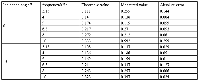
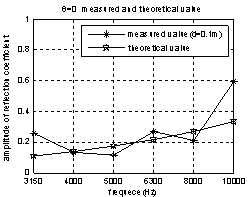
In figure 6,The incidence angle are 0ºand 15º,and frequency range from 3.15kHz~10kHz,the measured value is close to the theoretic value, sometimes the absolute error could ignore, the same state which can be found in table 2. In figure 7, the measure frequency is 4 kHz, incidence angle range from 0º~25º.
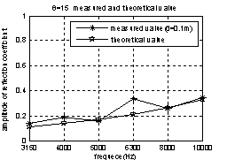
Fig. 7 the magnitude of reflection coefficient to frequency(incidence of the first is 0°,and the second incidence 15°;the measured value (*),theoretical value (☆))
Table 2 the absolute error with different angle at 4 kHz
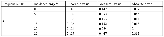
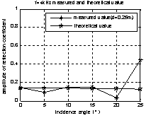
Fig. 7 the magnitude of reflection coefficient to angle(f=4kHz,the measured value (*),theoretical value (☆))
5 Conclution
Summary, this paper describes an effective method for measuring reflection coefficient with vector hydrophone, which measures pressure and particle velocity instantaneously, it cost less time, more accurate in measuring, handier in practice, and have good performance both in vertical and oblique incidence.
References
1. Zheng shijie,Yuan wenjun etc. underwater acoustic measuring technology[M].Harbin:Harbin Engineering University Press. pp.396-398,411-416(1995)
2. ISO 10534-1. Acoustics-Determination of sound absorption coefficient and impedance in impedance tubes-Part I: Method using standing wave ratio(1996)
3. Shi shengguo.Research on Vector Hydrophone and Its Application for Underwater Platform[D]Harbin: Doctor dissertation of Harbin Engineering University(2006)
4. He Xudong.The measurement of Reflection Coefficient of Underwater Acoustic Materials with Broad-band in Free Field[D]Harbin:Master dissertation of Harbin Engineering University(2010)
5. He Zuoyong, Zhao Yufang. Acoustic theory[M] National Defence Industry Press,pp. 91-92(1981)
6. R. Lanoye et al, a practical device to determine the reflection coefficient of acoustic materials in-situ based on a Microflown and microphone sensor, ISMA(2004)
7. R.Lanoye et al,Measuring the free field acoustic impedance and absorption coefficient of sound absorbing materials with a combined particle velocity-pressure sensor[J]J.A.S.A. 9(5):2826-2831(2006)
8. J.F.Allard, R. Bourdier etc. The measurement of acoustic impedance at oblique incidence with two microphones[J]. J. Sound. Vib. 101(1): 130- 132(1985)
[1] Xiaoer Wang (*), 3Dawei Zhang
Science and Technology on Underwater Acoustic Antagonizing Laboratory
Shanghai Marine Electronic Equipment Research Institute
Shanghai, China 201108
e-mail: xiaoer@126.com
2 Xiaoming Zhou
Laboratory of Underwater Acoustic Technology
College of Underwater acoustic engineering Harbin Engineering University
Harbin, China