毕业设计(论文)材料之二(2)

本科毕业设计(论文)开题报告
 题目: 可编程方波信号发生器电路设计

 课题类型: 设计
学生姓名: 张
学 号: 3080201220
专业班级: 自动化082
学 院: 电气工程学院
指导教师: 陈(正高级工程师)
开题时间: 2012年3月16日
20## 年3月16 日
1、毕业设计内容及研究意义
1.1 设计的内容
采用单片机为主控制器,产生0-10KHz的方波信号;该方波信号可在0-10KHz的范围内用键盘任意预置频率并采用数字显示方式显示输出频率;信号发生器可在预置的上、下限频率之间输出扫频方波信号。
1.2 研究意义
可编程方波信号发生器采用单片机控制,输出波形质量高、易于制作、性价比高,广泛应用于科研、教学和工业生产,有较高的应用和推广价值。信号发生器是科研及工程实践中最重要的仪器之一,以往多用硬件组成,系统结构比较复杂,可维护性和可操作性不加。随着计算机技术的发展,信号发生器的设计越来越多的是用计算机技术,利用单片机作为主控芯片进行控制。信号发生器所产生的信号在电路中常常用来代替前段电路的实际信号,为后端电路提供一个理想信号,由于信号源信号的特征参数均可人为设定,所以可以方便地模拟各种情况下不同特性的信号,对于产品研发和电路实验用着特别的意义。所以,本设计的应用前景相当广泛,具有更强的市场竞争力,在跳频技术、无线电通信技术方面具有比较广阔的应用前景。另外,本设计除了可以用作实验仪器外,还可以用在其它多种工作场合,对现在的工业生产控制有着举足轻重的意义,推动着这个工业生产和社会的进步。
2、毕业设计研究现状和发展趋势
2.1 研究现状
信号发生器是一种常用的信号源,广泛应用于电子电路、自动控制和科学实验等领域。它是一种为电子测量和计量工作提供符合严格技术要求的电信号设备。因此,信号发生和示波器、电压表、频率计等仪器一样是最普通、最基本的,也是应用最广泛的电子仪器之一,几乎所用的电参量的测量都需要用到信号发生器。
信号发生器是一种悠久的测量仪器,早在20年代电子设备出现时它就产生了。随着通信与雷达技术的发展,40年代出现了主要用于测试各种接收机的标准信号发生器,使信号发生器从定性分析的测试仪器发展成定量分析的测量仪器。同时还出现了可用来测量脉冲电路或用作脉冲调制器的脉冲信号发生器。由于早期的信号发生器机械结构比较复杂,电路比较简单,但功耗比较大,因此发展粗度比较慢。直到1964年才出现第一台全晶体管的信号发生器。自60年代以来信号发生器有了迅速的发展,出现了函数发生器,这个时期的信号发生器多采用模拟电子技术,由分立元件或模拟集成电路构成,其电路结构复杂,信号发生器的主要性能指标也有了大幅度的提高,同时在简化机械结构、小型化、多功能等方面也有了显著的进展,且仅能产生正弦波、方波、锯齿波和三角波等几种简单波形,由于模拟电路的漂移较大,使其输出的波形的幅度稳定性差,而且模拟器件构成的电路存在尺寸大、价格贵、功耗大等缺点,并且要产生较为复杂的信号波形则电路结构非常复杂。自从70年代微处理器出现以后,利用微处理器、模拟转换器和数模转换器,硬件和软件使信号发生器的功能扩大,产生比较复杂的波形。这时期的信号发生器多以软件为主,实质是采用微处理器对DAC的程序控制,就可以得到各种简单的波形。软件控制波形的一个最大缺点就是输出波形的频率低,这主要是由CPU的工作速度决定的,如果想要提高频率可以改进软件程序减少其执行的周期时间或提高CPU的时钟周期,但这些办法是有限的,根本的办法还是要改进硬件电路。随着现代电子、计算机和信号处理等技术的发展,极大地促进了数字化技术在电子测量仪器中的应用,使原有的模拟信号处理逐步被数字信号处理所代替,从而扩充了仪器信号的处理能力,提高了信号测量的准确度、精度和变换速度,克服了模拟信号处理的诸多缺点,数字信号发生器随之发展起来。
现在,随着大规模集成电路技术和计算机技术的飞速发展,信号发生器的设计越来越多的是用计算机技术,即利用单片机作为主控芯片进行控制。
2.2 发展趋势
信号发生器作为电子领域不可或缺的测量工具,它必然将向更高性能,更高精确度,更高智能化方向发展,就像数字化信号发生器的崛起一样。因此完整的方波信号发生器的设计具有非常重要的实践意义和广阔的应用前景。
3、毕业设计研究方案及工作计划
3.1 研究方案
本次毕业设计采用AT89S52单片机为主控器进行控制。系统主要由以下模块组成,包括键盘模块、振荡电路、单片机最小模块、显示模块以及输出模块等。通过键盘输入预值频率给主控芯片,经处理,通过LCD显示输出频率,经单片机最小模块处理后的信号经放大后输出描方波信号。
本次设计的系统结构框图如图1:
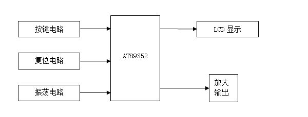 图1 系统结构框图
3.2 本课题工作计划

四、主要参考文献
[1] 陈海宴. 51单片机原理及应用[M].北京航空航天大学出版社,2010
[2] 王东峰等. 单片机C语言应用100例[M].电子工业出版社,2009
[3] 高士友,胡学深等. 基于FPGA的DDS信号发生器[J].现代电子技术,2009(5)
[4] 罗全,刘芝等. 基于FPGA的DDS信号源设计[J].广西师范学院学报,2009(2)
[5] 周德新,杨代文等. 基于FPGA的选择呼叫信号源设计[J].自动化仪表,2009(5)
[6] 唐琦,徐宏杰等. 基于DDS技术的动态偏振控制器驱动电路研究[J].现代电子技术2009(12)
[7] 余小平,奚大顺. 电子系统设计-基础篇(第二版) [M].北京航空航天大学出版社,2010
[8] 王峰. 基于数字频率合成芯片的复杂信号发生器[J].信息与电子工程2007,5(1)
[9] 张庆玲,王凡. 基于直接数字频率合成芯片的正弦信号发生器[J].电子测量技术,2008,31(9)
[10]Kaminsky, W.J.Davidson, E.S.Special Feature: Developing a Multiple-In-structon-Stream Single-Chip Processor. [J]Computer. 2008,12(12) : 66~67
[11]Sullvan GJ.Rate-distorrtion optimization for video compression. [J]IEEE Signal Processing.Mag.,2006,15(6)
[12]Bentley,John P,Priniple of Measurement Systems, [P]Longman,London and NewYork,2004
五、外文文献及翻译
英文原版:
MCS52 In-Circuit Programming
This application note illustrates the in-circuit programmability of the Atmel MCS52 Flash-based microcontroller. Guidelines for the addition of in-circuit programmability to MCS52applications are presented along with an application example and the modifications to it required supporting in-circuit programming. A method is then shown by which the MCS52microcontroller in the application can be reprogrammed remotely, over a commercial telephone line. The circuitry described in this application note supports five volt programming only, requiring the use of an MCS52-XX-5. The standard MCS52 requires 12 volts for programming. Circuitry added to support MCS52 in circuit programming should appear transparent to the application when programming is not taking place.
EA/VPP must be held high during programming. In applications which do not utilize external program memory, this pin may be permanently strapped to VCC. Applications utilizing external program memory require that this pin be held low during normal operation.
RST must be held active during programming. A means must be provided for overriding the application reset circuit, which typically asserts RST only briefly after power is applied.
PSEN must be held low during programming, but must not be driven during normal operation.
ALE/PROG is pulsed low during programming, but must not be driven during normal operation.
During programming, MCS52 I/O ports are used for the application of mode select, addresses and data, possibly requiring that the controller be isolated from the application circuitry. How this is done is application dependent and will be addressed here only in general terms.
Port Used for Input
During programming, the controller must be isolated from signals sourced by the application circuitry. A buffer with three state outputs might be inserted between the application circuitry and the controller, with the buffer outputs three-stated when programming is enabled. Alternately, a multiplexer might be used to select between signal sources, with signals applied to the controller by either the application circuitry or the programmer circuitry.
Port Used for Output
No circuit changes are required if the application circuitry can tolerate the state changes which occur at the port during programming. If the prior state of the application circuitry must be maintained during programming, a latch might be inserted between the controller and the application circuitry. The latch is enabled during programming, preserving the state of the application circuitry.
An Application Example
The MCS52 application shown in Figure 1 is an implementation of a moving display. This application was selected for its simplicity and ability to show graphically the results of in-circuit reprogramming. The text to be displayed is programmed into the controller as part of its firmware, and cannot be changed without reprogramming the device.
The displayed text is presented in one of two modes selected by the four-position DIP switch. In the first mode, one character at a time enters the display from the right and moves quickly to the left through each element of the display to its final position in the assembled message. In the second mode, the message moves through the display, from right to left, with the display acting as a window onto the message. This mode is familiar as the method often used in displays of stock prices.
The output consists of four DL1414T, four-digit, 17-segment alphanumeric displays with integral decoders and drivers. This yields 16 total display elements, each capable of displaying digits 0-9, the upper case alphabet, and some punctuation characters. The displayable character codes are ASCII 20H-5FH.
A power-on reset circuit and a 6-MHz crystal oscillator complete the application. Neither external program memory nor external data memory is used.
Modifications to the Application to Support
In-Circuit Programming Figure 2 shows the application modified for in-circuit programming.
It is assumed that the programmer, when inactive, will neither drive nor excessively load the application. Since the application does not use external program memory, EA/VPP on the controller is connected to VCC. This meets the requirement for programming.
The reset circuit has been modified by the addition of two transistors, which allow RST on the controller to be forced high by the programmer.
PSEN and ALE/PROG, unused in the basic application, are under the direct control of the programmer.
Programming requires programmer access to all of the four MCS52 I/O ports, as documented in the data sheet. The programmer is connected directly to those controller pins which are unused by the application, while access to pins used by the application requires special treatment, as explained in the following paragraphs.
The least significant four bits of the address generated by the programmer are multiplexed onto port one of the controller with the data from the DIP switch. Note that the four resistors added at the switch are not required in the basic application; since the MCS52 provides internal pull-ups on port one.
During the normal operation of the application, controller ports zero and two provide data and control signals (respectively) to the displays. During programming and program verification, the programmer asserts control of port zero and part of port two. The programmer is connected to ports zero and two without buffering, since, when inactive, its presence does not affect the normal operation of the application.
A transparent latch has been added between port two of the controller and the display control inputs. The latch holds the display control signals inactive during programming, which eliminates erratic operation of the displays due to programmer activity on ports zero and two. No isolation of the display data inputs is required, since data applied to the inputs is ignored when the control signals are inactive.
The MCS52 reset circuit, input multiplexer and output latch are controlled by a single signal generated by the programmer. During programming, reset is asserted, the multiplexer switches inputs, and the latch freezes the display control lines.
To ensure that the display control lines are in a known state before they are latched, an MCS52 external interrupt is used to allow the programmer to signal the application before asserting reset. The application firmware responds to the interrupt by displaying a message and deactivating the display control lines.
After programming, when reset is disserted, the controller ports are high as the latch becomes transparent. Since the display control inputs are inactive high, the display contents are not disturbed until the new program writes the display. Although not essential to this application, it might be imperative in some applications that the state of the peripheral circuitry not be disturbed during programming.
The Programmer
The programmer (Figure 3) generates the addresses, data and control signals necessary to program the MCS52 embedded in the application.
The programmer circuitry consists of an MCS52 and an RS-232 level translator. The controller runs at 11.0592 MHz, which allows the serial port to operate at a number of standard baud rates. A Maxim MAX232 line driver/receiver produces RS-232 levels at the serial interface while requiring only a five volt supply.
Many of the signals generated by the programmer are connected directly, without buffering, to the MCS52 in the application. These signals, when inactive, are not three stated, but are pulled high. The MCS52 has internal pull-ups of approximately three K ohms on ports one, two and three. Because port zero does not have internal pull-ups, external pull-ups of ten K ohms have been added to permit proper operation of program verification mode. The sample application operates correctly in this environment. If required for compatibility with an application, programmer signals may be buffered with three-state buffers similar to the 74xx125.
The MCS52 in the programmer does not utilize external program or data memory, which would require sacrificing needed I/O pins. This requires that program code and I/O buffers be kept small enough to fit in on-chip memory.
中文翻译:
单片机在编程电路中的应用
MCS52单片机是可在线可编程的微控制器。它为电路编程提出了相应的例子,程序的修改需要在线编程的支持。这类显示方法在应用程序中的52单片机可通过电话线远程控制。该应用指南所描述的电路只支持5v电压下编程。
当不在进行程序设计的时候,在电路设计中的52设计将变得透明化。
在编程期间必须重视EA/VPP这一脚。在不使用外部程序存储器的应用程序中,这脚可能会永久接到VCC。应用程序使用的外部程序存储器要求这一脚为低电平才能正常运行。
RST在编程期间必须为高电平。应该提供一种方法使得电路通入电源以后,使RST代替主要的复位电路起到复位的作用 。
在编程过程中,PSEN必须保持低电平,在正常运行期间绝不能使用。
ALE/ PROG在编程过程中输出低电平,在正常运行期间绝不能使用。
在编程过程中,MCS52的I / O端口是用于模式应用程序,地址和数据选择的,可能需要该控制器从应用的电路隔离。如何做到这一点取决于应用程序。
输入端口
在编程过程中,控制器必须与应用电路的信号来源隔离。带有三个输出状态的缓冲区会在应用程序之间插入电路和控制器,同时在编程时缓冲区输出三种状态。一个多路复用器可用于信号源之间进行选择,适用于任何一方的应用电路或编程控制器电路的信号。
输出端口
如果应用的电路可以允许端口在编程过程中的状态变化,则不需要改变电路。如果应用电路的状态,必须事先在编程过程中的保持不变,可能在控制器和应用电路中插入锁存。锁存在编程期间是可用的,并保存应用程序的电路状态。
应用实例
应用是该MCS52一个移动的显示情况。此应用程序有在电路重新编程时将结果以图表的形式显示的简单能力。文本显示被设计作为其硬件的一部分,不能在无改编情况下变化。
显示的文本可在4位DIP开关选择两种模式之一中进行。在第一种模式的时候,进入一个字符从右边显示和快速移动,通过每个元素显示其在最后的装配位置的左侧。在
第二个模式,信息在信息窗口中右到左移动显示。这种模式与常常在股票价格的显示器所使用的方法类似。
输出包括四个DL1414T,4位17段的积分解码器和驱动程序的字母数字显示器。这就产生了16名显示元素,每个数字有0-9的显示能力,是大写字母,标点符号和一些字符。可显示字符的ASCII 码,范围为20H-5FH。上电复位电路和一个6 MHz的晶体振荡器完成应用软件程序。无论外部程序存储器或外部数据存储器都时可用的。
支持应用程序的修改
据推测,编程器在休眠时,既不会驱动,也不会加载应用程序。由于应用程序不使用外部程序存储器,EA/VPP脚接VCC电源。复位电路被两种转换器改变状态,此转换器允许编程时RST接高电平。在基本应用时未使用的PSEN和ALE/ PROG,是被程序员直接控制的。
编程器的编程需要获得所有数据表中记录的MCS52的I / O端口。编程器是与那些应用程序未使用的控制器的引脚相连的,而这些应用程序的引脚需要最低有效位的四所产生的地址是可获得的,如下段所述。
由编程器生成的最小的四位地址是与DIP转换的数据在控制器的端口多路复用的。
请注意,加在开关上的四个电阻在基本应用中并不是必须的,因为MCS52的端口上提供一个内部上拉电阻。
在应用程序的正常运作时,控制器端口0,1个分别在显示器上提供数据和控制信号。在编程和程序验证时,编程受端口0和端口2的一部分控制。程序设计器连接端口0和1,没有缓冲,因为,在不活动时,它的存在不影响应用程序的正常运作。
透明锁存器被加在了控制器的两个端口之间做输入控制。锁存持有的显示控制信号在编程过程中不反应,从而消除端口0和2由于程序控制器的活动造成操作失误。显示数据输入是不能被孤立的,因为数据应用到输入被忽略时,控制信号无效。
MCS52单片机复位电路,输入多路复用器和输出锁存器是由程序控制器生成一个单一的信号来控制的。在编程过程中,复位键生效,多路开关信号输入,以及冻结显示锁存控制线。
为确保控制线显示在已知的状态前锁定,MCS52的外部中断是用来允许程序控制器在复位之前向应用程序发出信号。应用程序固件响应中断显示一条消息,关闭显示控制线。
编程后,当复位生效,当锁存可视控制器端口输出高电平。由于显示控制输入不为高电平,直到新的程序写入显示器内部不被打乱。虽然这个应用程序是没有必要的,它可能在某些应用中必须指出,在编程过程中不会扰乱外围电路的状态
程序控制器
程序控制器生成的地址,数据和控制信号,对嵌入到程序中的MCS52有重要作用。
程序控制器电路由一个MCS52和一个RS - 232电平转换器组成。该控制器运行在11.0592兆HZ,此频率允许串口运行在一个标准波特率下。一个MAXIM MAX232线路驱动器/接收器产生RS - 232水平,而只需要5伏的电源系统。
程序控制器所产生的信号许多只需直接连接到MCS52,无需缓冲。这些信号,在不活动时,不再是三种状态,但被接高电平。MCS52的端口1,2,3内部有大约3000欧姆的上拉电阻,因为端口0没有内部上拉电阻,所以外部10千欧姆的上拉电阻已经加上允许适当的程序认证模式操作。示例应用程序在这种环境下可正常运行。如果有需要的应用程序兼容性,程序发出的信号可能在类似74xx125三态缓冲缓冲区内缓冲。
MCS52的程序不使用外部程序或数据存储器,这需要牺牲所需要的I / O引脚。这就要求程序代码和I / O缓冲区保持足够小以适合片上存储器。