Lab 4 Experiment of heat transfer
I. Objectives
1. Measure the overall heat-transfer coefficient K for a double-tube heat exchanger and the film heat-transfer coefficient for the inside of a circular pipe.
2. Measure the correlation between the Nusselt number Nu and the Reynolds number Re for heat transfer by forced convection in turbulent flow in a tube.
II. Principle
Heat transfer from a warmer fluid to a cooler fluid, usually through a solid wall separating the two fluids, is common in chemical engineering practice.
1. Determination of the overall heat transfer coefficient K
In the light of the equation of overall heat flow rate
 (1.15)
Equation (1.15) can be written as
 (1.16)
where Q = rate of heat transfer in the exchanger, W
A = total area of heat transfer surface, m2
 = logarithmic mean temperature difference, ℃
The overall coefficient K can be determined if the values of Q, A and are measured or given.
(1) Rate of heat transfer
In this experiment, steam flows through the annular space between the outside and the inside pipe and air flows through the inside pipe. Hence, the overall energy balance equation can be obtained, neglecting the heat loss.
 (1.17)
where qmh = mass flux of steam condensed, kg/s
qmc = mass flux of air, kg/s
rh = vaporization heat of water, J/kg
cp c =specific heat of air at a constant pressure, J/(kg·K)
t1 =temperature of inlet air, ℃
t2 =temperature of outlet air, ℃
The rate of heat transfer in the exchanger Q is calculated according to the heat gained by air. The air flow rate is measured with an orifice meter and its mass flux is
 (1.18)
 (1.19)
where qV = volumetric flow rate of air, m3/s
C0 = orifice coefficient, here C0=0.855
A0 = area of orifice, , here d0=0.023 m
ρ = air density at the inlet of the orifice meter, kg/m3
ρ0 = indicator density of differential pressure meter, kg/m3
R = reading of differential pressure meter, mm
Air density can be calculated according to the ideal gas law.
 (1.20)
where pa =local atmospheric pressure, Pa
t = air temperature of the inlet of the orifice meter,℃
R =gauge pressure of the inlet of the orifice meter, Pa
(2) Logarithmic mean temperature difference,
 (1.21)
where T = steam temperature, ℃
t1= temperature of inlet air, ℃
t2= temperature of outlet air, ℃
(3) Total area of heat transfer surface, A
A=πdL (1.22)
where L= length of heat-transfer tube, m
d=outside diameter of tube, m
2. Measurement the film heat-transfer coefficient, α
For the heat-transfer between air and steam, if the heat resistance of pipe wall and the fouling resistance are negligible, then the relationship of the overall coefficient of heat transfer and the film coefficient of heat transfer is expressed as
 (1.23)
where α1=film coefficient of heat transfer from pipe wall to air, W/(m2·K)
α2 =film coefficient of heat transfer from steam to pipe wall, W/(m2·K)
For the film heat-transfer coefficient for the inside of the tube greater than that for the outside of the pipe for this experiment, the overall heat-transfer coefficient K approximately equals the film coefficient for the inside of the pipe.
 (1.24)
3. The empirical relation of Nu and Re
Based on dimensional analysis, the film heat-transfer coefficient of air for turbulent flow inside the tube conforms to the following equation.

or  (1.25)
where Nu = Nusselt number
Re = Reynolds number
λ= air thermal conductivity, W/(m·K)
u = air flow velocity, m/s
ρ= air density, kg/m3
μ= air viscosity, kg/(m·s)
A, n=coefficients to be determined
In this experiment, the film heat-transfer coefficient can be measured by adjusting the air flow rate. Then, plot a Nu-Re curve on a double logarithmic paper and to determine coefficients of A and n. An empirical equation of the relationship between the film heat-transfer coefficient α and Re can be obtained.
III. Apparatus
The setup is consisted of two double-pipe exchangers. The inside pipe for one is made from a smooth brass pipe, and that for the other is made from a screwed slot brass pipe. The outside pipe for both exchangers is steel pipe.

Fig. 1.6 Heat transfer in a double-pipe heat exchanger between vapor and air
1—air blower; 2—orifice flow meter; 3—air regulating valve; 4—double pipe heat exchanger;
5—viewing mirror; 6—thermometer; 7—thermal couple; 8—safe valve; 9—steam pressure gauge;
10—manometer; 11—steam inlet valve; 12—blow-down cock; 13—steam trap;
14—alternation switch of thermal couple; 15—differential electrometer; 16—ice pot
IV. Experimental procedures
1. Prime the tap water into the water tank of the steam generator. When the water level reaches the red line of water level gauge, switch on the power, and open the air discharge valve to drain non-condensable gases.
2. When the water is boiling, switch off one or two sets of heater, then regulate the temperature controller to a given value.(normally the temperature is less than 135℃).
3. Check the above steps and proceed.
4. During the period of operation,the water level must be between upper and lower red lines. If the water level is below the red line, switch off the power, open the air discharge valve, and refill water.
5. When the steam pressure reaches a certain value (0.1MPa), start the air blower, open steam inlet valve, and regulate the air flowrate. Measure 6 to 8 sets of data for suitable flowrate intervals. During the operation, open the air discharge valve regularly to drain the non-condensable gases.
6. Switch off the power and the differential electrometer, open the air discharge valve, and stop the air blower.
V. Cautions
1. Control the stream pressure not to exceed the pressure limit. Observe the water level of the water tank.
2. During the experiment, the joint point of the thermal couple should be placed in an ice pot to keep it around zero degree.
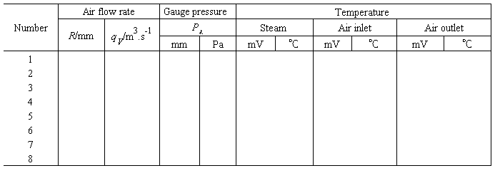
VI. Data records
outside diameter of pipe: ㎜; pipe length: m;
flow coefficient: ; room temperature: ℃
Table 1.4 Data records for heat transfer experiment
VII. Report objectives
1. Fill the experimental data into the data log.
2. Plot the Nu-Re curve on a double logarithmic paper and determine coefficients of A and n. Express the experimental data in the form of the empirical equation (1.25).
VIII. Questions
1. Why use the Nu-Re equation instead of the relationship between Nu and air flowrate?
2. Why the total heat transfer coefficient K approximately equals to film heat-transfer coefficient?
3. 2。为什么总传热系数K约等于膜传热系数?
4. If the stream pressure changes, any effects on the film coefficient of heat transfer?
5. 。如果流压力变化,任何影响传热膜系数?
6. Any effects of air humidity and temperature on the film heat-transfer coefficient?
。任何影响空气的湿度和温度对膜传热系数