电子设计自动化实验研究论文
摘 要
Altium Designer 6.0,它是完全一体化电子产品开发系统的一个新版本,也是业界第一款也是唯一一种完整的板级设计解决方案。Altium Designer 是业界首例将设计流程、集成化 PCB 设计、可编程器件(如 FPGA)设计和基于处理器设计的嵌入式软件开发功能整合在一起的产品,一种同时进行PCB和FPGA设计以及嵌入式设计的解决方案,具有将设计方案从概念转变为最终成品所需的全部功能。 关键字:Altium Designer、仿真、电子技术
目 录
摘要. i
目录. ii
第1章.前言
第2章.电路原理图的绘制与仿真
2.1. 了解Altium Designer的界面及基本操作。
2.2. 学会使用Altium Designer绘制电路原理图。
2.3. 绘制一个555闪光电路的原理图。
2.4. 对该电路进行仿真分析。
第3章.印制电路板的设计和制作
3.1.印制电路板设计的一般步骤。
3.2. 熟悉印制电路板图设计界面和各种工具的使用。
3.3. 绘制印制电路板图
3.4. 生成元件清单,根据此清单购买所需的元件。
第4章.实际电路的制作和调试
4.1. 认识元器件。
4.2. 焊接电路与通电检测。
4.3. 观察并分析电路现象。
第5章结论.
致谢.
参考文献.
第1章 前言
随着现代集成电路技术及其配套的计算机软件技术的快速发展,使得复杂的电路设计简单化。一方面,集成电路把整个电路封装在一个很小的外壳里,所以你只要挑选好合适的集成电路块就行了,不必用晶体管和其它元件来组成工作电路的各个部分。然后你可以把那些集成电路块组合起来构成非常复杂的电路。另一方面,随着EDA软件的大量涌现,过去需要进行的面包板实验和试验电路板的制作也已经被计算机软件仿真逐步取代。
在折中考虑软件的仿真能力和印制电路板的绘制的便利性上,本实验将以Altium公司的新一代集成一体化设计软件Altium Designer作为基础进行。我们为同学们提供了一些关于此软件的简单使用的视频讲义和教程,但是对于如此庞大、功能如此强大的一套软件系统来说,这一点材料是远不足够的,所以,还请感兴趣的同学寻找一些额外的资料来阅读和学习。
第2章.电路原理图的绘制与仿真
2.1. 了解Altium Designer的界面及基本操作
(1)单击/开始/程序/Altium Designer Winter09/Altium Designer Winter09 进入主界面。
(2)启动进入Altium Designer的主界面后,点击左上角的DXP/Preferences命令。将System/General中的Localization栏中的Use localized resources选项的钩上,可将Altium Designer转换到中文界面。
注意:由于这个中文化是不完全的,所以不建议大家使用。
(3)执行File/New/Project/PCB Project命令,当弹出选择PCB类型的对话框时,选择PCB类型Protel Pcb。执行File/Save Project As命令将该项目的名称命名为(555flash_学号.PrjPCB),把项目存放在指定的目录中,即D:\学号\。
(4)执行File/New/Schematic,建立电路图文件,之后进入电路图设计主界面。
(5)配合视频讲义,熟悉各窗口、工作条以及任务菜单的名称及用途。
(6)配合视频讲义,学习如何在工作平面上放置元件。特别注意电气节点的意义。
2.2学会使用Altium Designer绘制电路原理图
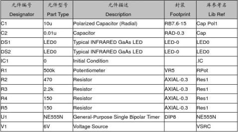
图1.1所示的是最简单的一种闪光电路。这种电路利用两只发光二极管,时暗时明地闪闪发光。下面我们介绍如何绘制该电路原理图。
(1)建立一个空白的原理图文档,将其另存为555flash.SchDoc。
(2)点击右侧边栏上的Libraries按钮,弹出元件库对话框,选择Libraries,再选择Installed标签,分别添加Miscellaneous Connectors.IntLib集成库、Miscellaneous Devices.IntLib,以及Simulation目录下的各仿真单元库。
(3)在单元库中寻找所需要的元件并放置。
(4)按照实验内容1中学会的方法绘制和图1.1相同的电路原理图。所需的元件相关情况请参照表1.1。
(5)元件的编号可使用Tools/Annotate,在弹出对话框后点击Update Changes List按钮后确定,再点击Accept Changeds按钮,最后点击Execute Changes按钮即可。
提示:电阻的元件名称为RES,意为Resistor的简写。电容的元件名称为CAP。所用到的所有元件均可在以上库中找到。如遇找不到的元件时可使用查找按钮,输入所要查找的元件名称进行查询,如需要查找555集成块,可输入*555*进行查询。
2.3. 绘制一个555闪光电路的原理图。
图1.1 实验电路原理图
2.4. 对该电路进行仿真分析。
为了对前面设计555闪光电路进行仿真,我们需要对电路原理图作一定程度上的修改。 (1)双击NE555N或者选中NE555N后点右键选择Properites,在Models for NE555N列表框中点击Add按钮。选择模型类型为―Simulation‖,选择模型子种类中的―Spice Subcircuit‖,并将Model Name改为555B,Description改为SUBCKT。模型位置使用Full Path,使用实
验提供的555B.ckt文件。点击Port Map标签将原理图引脚和模型引脚一一对应,即1对1,2对2,以此类推。
(2)双击电阻R1进入属性对话框,编辑Models for R1中的Simulation类型。选择Parameters标签,将其中的Value值改为R1的给定值500K,并将Set Position设为0.99,实际电阻值为(Value – Value * Set Position)。
(3)按照以上方法,将其他元件的模型参数值一一进行修改为给定值一便进行下一步的仿真。
(4)点击Design/Simulation/Mixed Sim命令打开分析设定对话框。
(5)从分析选项列表框中选择Transient/Fourier Analysis(瞬态特性分析/傅里叶分析)选项条。去掉Use Transient Defaults选项前的小勾,设置Transient Start Time为0,Transient Stop Time为1s,Transient Step Time和Transient Maximum Step均为1ms。
(6)从可用信号列表中将信号OUT加入到Active信号列表中,并将SimView设定改为Show active signals。OUT信号在仿真结束后将自动显示。点击―确认‖进行仿真。
(7)如果有错误产生,返回电路原理图进行检查,解决错误后再进行仿真。
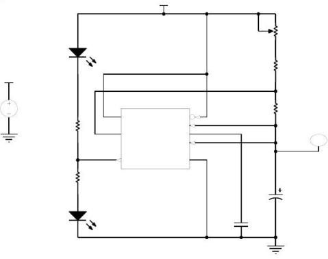
(8)观察并分析仿真结果,如要显示其他波形可使用位于左侧的SimData对话框,任选一个波形点击加波形到图即可。其中需要说明的是*[i]和*[p]分别表示该元件上的电流和功率。如想要察看波形的具体信息可以点击/波形/光标A和光标B后拖动即可,信息将在SimData的测量光标栏中显示。如图1.2所示。
第3章.印制电路板的设计和制作
3.1.印制电路板设计的一般步骤。
(1)规划电路板。
在绘制电路板之前,用户要对电路板的有一个初步的规划,比如说电路板采用多大的物理尺寸,采用几层电路板,是单面板还是多面板,各元器件采用何种封装及其安放位置等。这是一项极其重要的工作,是确定电路板设计的框架。
(2)设置参数。
参数的设置是电路板设计的非常重要的步骤。设置参数主要是设置元器件的布置参数、板层参数、布线参数等等。一般来说,有些参数用其默认值即可,有些参数在使用过Altium Designer以后,即第一次设置后,以后几乎无需修改。
(3)装入网络表及元件封装。
网络表是电路板自动布线的灵魂,也是电路原理图设计系统与印制电路板设计系统的接口。因此这一步也是非常重要的环节。只有将网络表装入之后,才可能完成对电路板的自动布线。元器件的封装就是元器件的外形,对于每个装入的元器件必须有相应的外形封装,才能保证电路板布线的顺利进行。
3.2. 熟悉印制电路板图设计界面和各种工具的使用。
(1)启动进入Altium Designer得主界面后,进入上次实验使用的项目中。
(2)执行/File/New/PCB文件命令,建立一个PCB文件。
(3)进入设计界面后,根据视频讲义,熟悉各操作命令的名称和用途
3.3. 绘制印制电路板图
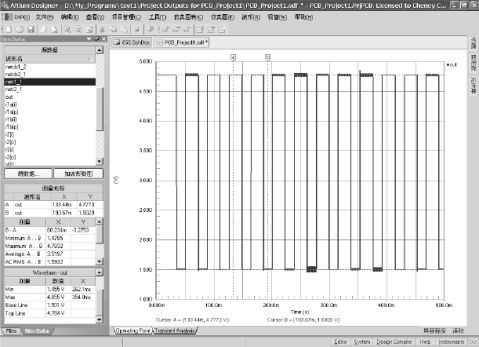
(1)新建一个PCB文件,采用同前的命名方式555flash.PcbDoc。执行/Design/Board Options命令,系统将弹出PCB板选择项对话框。转到上次实验绘制的电路原理图中,将电路原理图修改或新建如图 2.1所示。

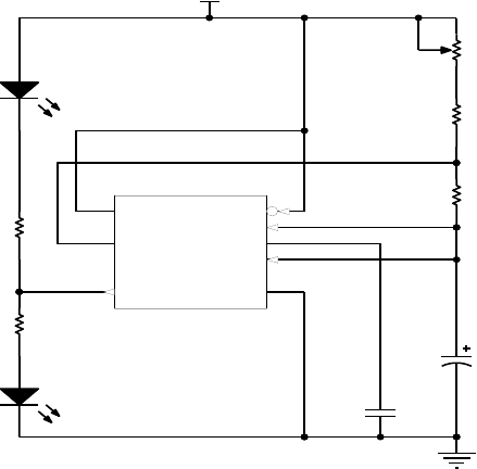
图2.1 修改后的实验电路原理图
(2)使用Tools/Component Placement/Auto Placer命令,分别使用两种放置方法进行布局并观察结果。最后使用手工调整元件到你觉得合适的位置。图2.2显示的是经过自动布局
和手工调整后的一种电路布局方案。
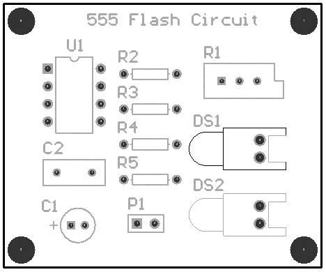
图2.2 经调整后的电路布局方案
3.4. 生成元件清单,根据此清单购买所需的元件。
返回电路原理图,点击Reports/Bill of Material命令,生成一份元件列表清单。根据此清单购买所需要的各种元器件,为下次实验做准备。
第4章.实际电路的制作和调试
4.1. 认识元器件
(1)认识各元器件的实际外观、封装。
(2)测量几种典型元件的管脚的尺寸并和软件中使用封装进行比较。
(3)使用万用表测量各元件,观察元件标称值和实际值之间的误差。
4.2. 焊接电路与通电检测
(1)根据上两次实验所绘制的实验电路原理图和印制电路板图焊接电路。
(2)检查焊接的电路有否存在短路,断路,焊接等可能存在的错误。
(3)确认没有错误后,通电检测电路。观察现象是否和设计目标一致。发光二极管是否可以闪动。
4.3. 观察并分析电路现象
该电路实际上是一个由555构成的多谐振荡电路。该电路的时间参数可由多谐振荡电路公式计算T1=(R1+R2+R3)Cln2, T2=R3Cln2, q=(R1+R2)/(R1+R2+R3),结合实验一中的仿真方法,比较理论计算值、软件仿真值和实际观察值之间的差别。
例如:当R1=0K,R2=470,R3=2.2K时。
(1)理论计算值为:T1≈0.0185s T2≈0.0152s T=T1+T2=0.0337s f=1/T≈29.67Hz
(2)仿真波形如图3.1所示。从该仿真波形的测量结果可看出:T1≈0.0186s,T2≈0.0159,
T=0.0344s,f=1/T=29.07这个结果和理论计算值是一致的。这种程度的误差在实际电路中完全可以忽略。
(3)实际观察值。使用示波器对输出波形进行观察。
在R1为0时,T1≈0.020s,T2≈0.017s,T=0.037,f=1/T=27Hz。这个频率略低于理论值和仿真值,这是因为实际的可变电阻器不可能真正将其阻值变为0,此外,从实验内容1中大家可以清楚地认识到所有的元件度不可能精确的达到其标称值,这也就使得实际电路并不可能产生和理论分析同样的结果。
5.93V
4.00V
2.00V
1.43V
40ms
V(3)60ms80ms
Time100ms120ms
图3.1 一个仿真波形图
第5章 结论
? 使用软件仿真具有以下优点:
不需要试验电路板;具有检测电路任一信号的能力;能够将反馈环路拆开;可以方便地修改电路;可在不同温度下对电路进行分析。
? 但是计算机仿真也有一些缺点:
仿真的结果受到仿真时使用的模型影响;
有时由于不收敛而得不到结果;对大电路进行仿真很费时间;无法使用计算机代替人的思维。
适当地进行计算机软件仿真可以大大的节省电路设计环节中,验证性能指标和修改电路参数所需的时间,但是也需要注意到仿真软件的局限性和建立试验电路板的不可替代性。任何条件下仿真和现实结果都是有出入的。所以本实验要求我们搭建试验电路板进行最后的分析,最后的实际分析结果与仿真结果基本相似,但存在一定的误差。
参考文献:《实验讲义》、视屏资料
第二篇:电气与信息学院自动化专业毕业设计(论文)外文翻译-电子动力转向系统的研究与设计
电气与信息学院自动化专业毕业设计(论文)外文翻译
Electonic power steering system Research and Design
电子动力转向系统的研究与设计
注:本毕业设计(论文)外文翻译文档前半部分为英文部分,后半部分为中文部分。本外文翻译由专业人员翻译,内容详细数据全面,得到导师的一致好评。值得大家借鉴参考。本文档下载后为WORD版本,可按需直接编辑。
Electronic power steering system

What it is
Electrically powered steering uses an electric motor to drive either the power steering hydraulic pump or the steering linkage directly. The power steering function is therefore independent of engine speed, resulting in significant energy savings.
How it works :
Conventional power steering systems use an engine accessory belt to drive the pump, providing pressurized fluid that operates a piston in the power steering gear or actuator to assist the driver.
In electro-hydraulic steering, one electrically powered steering concept uses a high efficiency pump driven by an electric motor. Pump speed is regulated by an electric controller to vary pump pressure and flow, providing steering efforts tailored for different driving situations. The pump can be run at low speed or shut off to provide energy savings during straight ahead driving (which is most of the time in most world markets).
Direct electric steering uses an electric motor attached to the steering rack via a gear mechanism (no pump or fluid). A variety of motor types and gear drives is possible. A microprocessor controls steering dynamics and driver effort. Inputs include vehicle speed and steering, wheel torque, angular position and turning rate.
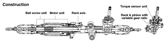
Working In Detail:

A "steering sensor" is located on the input shaft where it enters the gearbox housing. The steering sensor is actually two sensors in one: a "torque sensor" that converts steering torque input and its direction into voltage signals, and a "rotation sensor" that converts the rotation speed and direction into voltage signals. An "interface" circuit that shares the same housing converts the signals from the torque sensor and rotation sensor into signals the control electronics can process.
Inputs from the steering sensor are digested by a microprocessor control unit that also monitors input from the vehicle's speed sensor. The sensor inputs are then compared to determine how much power assist is required according to a preprogrammed "force map" in the control unit's memory. The control unit then sends out the appropriate command to the "power unit" which then supplies the electric motor with current. The motor pushes the rack to the right or left depending on which way the voltage flows (reversing the current reverses the direction the motor spins). Increasing the current to the motor increases the amount of power assist.
The system has three operating modes: a "normal" control mode in which left or right power assist is provided in response to input from the steering torque and rotation sensor's inputs; a "return" control mode which is used to assist steering return after completing a turn; and a "damper" control mode that changes with vehicle speed to improve road feel and dampen kickback.
If the steering wheel is turned and held in the full-lock position and steering assist reaches a maximum, the control unit reduces current to the electric motor to prevent an overload situation that might damage the motor. The control unit is also designed to protect the motor against voltage surges from a faulty alternator or charging problem.
The electronic steering control unit is capable of self-diagnosing faults by monitoring the system's inputs and outputs, and the driving current of the electric motor. If a problem occurs, the control unit turns the system off by actuating a fail-safe relay in the power unit. This eliminates all power assist, causing the system to revert back to manual steering. A dash EPS warning light is also illuminated to alert the driver. To diagnose the problem, a technician jumps the terminals on the service check connector and reads out the trouble codes.
click here to see a bigger 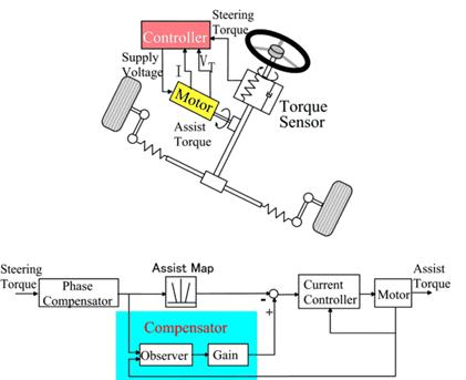
Electric power steering systems promise weight reduction, fuel savings and package flexibility, at no cost penalty.
Europe's high fuel prices and smaller vehicles make a fertile testbed for electric steering, a technology that promises automakers weight savings and fuel economy gains. And in a short time, electric steering will make it to the U.S., too. "It's just just a matter of time," says Aly Badawy, director of research and development for Delphi Saginaw Steering Systems in Saginaw, Mich. "The issue was cost and that's behind us now. By 20## here in the U.S. the cost of electric power steering will absolutely be a wash over hydraulic."
Today, electric and hybrid-powered vehicles (EV), including Toyota's Prius and GM's EV-1, are the perfect domain for electric steering. But by 2010, a TRW Inc. internal study estimates that one out of every three cars produced in the world will be equipped with some form of electrically-assisted steering. The Cleveland-based supplier claims its new steering systems could improve fuel economy by up to 2 mpg, while enhancing handling. There are true bottom-line benefits as well for automakers by reducing overall costs and decreasing assembly time, since there's no need for pumps, hoses and fluids.
Another claimed advantage is shortened development time. For instance, a Delphi group developed E-TUNE, a ride-and-handling software package that can be run off a laptop computer. "They can take that computer and plug it in, attach it to the controller and change all the handling parameters -- effort level, returnability, damping -- on the fly," Badawy says. "It used to take months." Delphi has one OEM customer that should start low-volume production in '99.Electric steering units are normally placed in one of three positions: column-drive, pinion-drive and rack-drive. Which system will become the norm is still unclear. Short term, OEMs will choose the steering system that is easiest to integrate into an existing platform. Obviously, greater potential comes from designing the system into an all-new platform. "We have all three designs under consideration," says Dr. Herman Strecker, group vice president of steering systems division at ZF in Schwaebisch Gmuend, Germany. "It's up to the market and OEMs which version finally will be used and manufactured." "The large manufacturers have all grabbed hold of what they consider a core technology," explains James Handy sides, TRW vice president, electrically assisted steering in Sterling Heights, Mich. His company offers a portfolio of electric steering systems (hybrid electric, rack-, pinion-, and column-drive). TRW originally concentrated on what it still believes is the purest engineering solution for electric steering--the rack-drive system. The system is sometimes refer to as direct drive or ball/nut drive. Still, this winter TRW hedged its bet, forming a joint venture with LucasVarity. The British supplier received $50 million in exchange for its electric column-drive steering technology and as sets. Initial production of the column and pinion drive electric steering systems is expected to begin in Birmingham, England, in 2000.
"What we lack is the credibility in the steering market," says Brendan Conner, managing director, TRW/LucasVarity Electric Steering Ltd. "The combination with TRW provides us with a good opportunity for us to bridge that gap." LucasVarity currently has experimental systems on 11 different vehicle types, mostly European. TRW is currently supplying its EAS systems for Ford and Chrysler EVs in North America and for GM's new Opel Astra.
In 1995, according to Delphi, traditional hydraulic power steering systems were on 7596 of all vehicles sold globally. That 37-million vehicle pool consumes about 10 million gallons in hydraulic fluid that could be superfluous, if electric steering really takes off.
The present invention relates to an electrically powered drive mechamsm for providing powered assistance to a vehicle steering mechanism. According to one aspect of the present invention, there is provided an electrically powered driven mechanism for providing powered assistance to a vehicle steering mechanism having a manually rotatable member for operating the steering mechanism, the drive mechanism including a torque sensor operable to sense torque being manually applied to the rotatable member, an electrically powered drive motor drivingly connected to the rotatable member and a controller which is arranged to control the speed and direction of rotation of the drive motor in response to signals received from the torque sensor, the torque sensor including a sensor shaft adapted for connection to the rotatable member to form an extension thereof so that torque is transmitted through said sensor shaft when the rotatable member is manually rotated and a strain gauge mounted on the sensor shaft for producing a signal indicative of the amount of torque being transmitted through said shaft. Preferably the sensor shaft is non-rotatably mounted at one axial end in a first coupling member and is non-rotatably mounted at its opposite axial end in a second coupling member, the first and second coupling members being inter-engaged to permit limited rotation there between so that torque under a predetermined limit is transmitted by the sensor shaft only and so that torque above said predetermined limit is transmitted through the first and second coupling members. The first and second coupling members are preferably arranged to act as a bridge for drivingly connecting first and second portions of the rotating member to one another. Preferably the sensor shaft is of generally rectangular cross-section throughout the majority of its length. Preferably the strain gauge includes one or more SAW resonators secured to the sensor shaft. Preferably the motor is drivingly connected to the rotatable member via a clutch .Preferably the motor includes a gear box and is concentrically arranged relative to the rotatable member. Various aspects of the present invention will hereafter be described, with reference to the accompanying drawings, in which :Figure 1 is a diagrammatic view of a vehicle steering mechanism including an electrically powered drive mechanism according to the present invention, Figure 2 is a flow diagram illustrating interaction between various components of the drive mechanism shown in Figure 1 ,Figure 3 is an axial section through the drive mechanism shown in Figure 1, Figure 4 is a sectional view taken along lines IV-IV in Figure 3,Figure 5 is a more detailed exploded view of the input drives coupling shown in Figure 3, and Figure 6 is a more detailed exploded view of the clutch showing in Figure 3. Referring initially to Figure 1 , there is shown a vehicle steering mechanism 10 drivingly connected to a pair of steerable road wheels The steering mechanism 10 shown includes a rack and pinion assembly 14 connected to the road wheels 12 via joints 15. The pinion(not shown) of assembly 14 is rotatably driven by a manually rotatable member in the form of a steering column 18 which is manually rotated by a steering wheel 19.The steering column 18 includes an electric powered drive mechanism 30 which includes an electric drive motor (not shown in Figure 1) for driving the pinion in response to torque loadings in the steering column 18 in order to provide power assistance for the operative when rotating the steering wheel 19.As schematically illustrated in Figure 2, the electric powered drive mechanism includes a torque sensor20 which measures the torque applied by the steering column 18 when driving the pinion and supplies a signal to a controller 40. The controller 40 is connected to a drive motor 50 and controls the electric current supplied to the motor 50 to control the amount of torque generated by the motor 50 and the direction of its rotation. The motor 50 is drivingly connected to the steering column 18 preferably via a gear box 60, preferably an epicyclic gear box, and a clutch 70. The clutch 70 is preferably permanently engaged during normal operation and is operative under certain conditions to isolate drive from the motor 50 to enable the pinion to be driven manually through the drive mechanism 30. This is a safety feature to enable the mechanism to function in the event of the motor 50 attempting to drive the steering column too fast and/or in the wrong direction or in the case where the
motor and/or gear box have seized.
The torque sensor 20 is preferably an assembly including a short sensor shaft on which is mounted a strain gauge capable of accurately measuring strain in the sensor shaft brought about by the application of torque within a predetermined range. Preferably the predetermined range of torque which is measured is 0-lONm; more preferably is about l-5Nm.Preferably the range of measured torque corresponds to about 0-1000 microstrain and the construction of the sensor shaft is chosen such that a torque of 5Nm will result in a twist of less than 2° in the shaft, more preferably less than 1 ° .Preferably the strain gauge is a SAW resonator, a suitable SAW resonator being described in WO91/13832. Preferably a configuration similar to that shown in Figure 3 of WO91/13832 is utilised wherein two SAW resonators are arranged at 45° to the shaft axis and at 90° to one another. Preferably the resonators operate with a resonance frequency of between 200-400 MHz and are arranged to produce a signal to the controller 40 of 1 MHz ± 500 KHz depending upon the direction of rotation of the sensor shaft. Thus, when the sensor shaft is not being twisted due to the absence of torque, it produces a 1 MHz signal. When the sensor shaft is twisted in one direction it produces a signal between 1.0 to 1.5 MHz. When the sensor shaft is twisted in the opposite direction it produces a signal between 1.0 to 0.5 MHz. Thus the same sensor is able to produce a signal indicative of the degree of torque and also the direction of rotation of the sensor shaft. Preferably the amount of torque generated by the motor in response to a measured torque of between 0-10Nm is 0-40Nm and for a measured torque of between l-5Nm is 0-25Nm.Preferably a feed back circuit is provided whereby the electric current being used by the motor is measured and compared by the controller 40 to ensure that the motor is running in the correct direction and providing the desired amount of power assistance. Preferably the controller acts to reduce the measured torque to zero and so controls the motor to increase its torque output to reduce the measured torque. A vehicle speed sensor (not shown) is preferably provided which sends a signal indicative of vehicle speed to the controller. The controller uses this signal to modify the degree of power assistance provided in response to the measured torque. Thus at low vehicle speeds maximum power assistance will be provided and a high vehicle speeds minimum power assistance will be provided。 The controller is preferably a logic sequencer having a field programmable gate array for example a XC 4005 as supplied by Xilinx. Such a controller does not rely upon software and so is able to function more reliably in a car vehicle environment. It is envisaged that a logic sequence not having a field programmable array may be used.
Electronic power steering system (English as EPS), and hydraulic power steering system (HPS) compared to, EPS has many advantages.
The advantage is that the EPS:
1) high efficiency. HPS efficiency is very low, generally 60% to 70%, while EPS and electrical connections, high efficiency, and some can be as high as 90 percent.
2) less energy consumption. Automobile traffic in the actual process, at the time to about 5 percent of the time travelling, the HPS system, engine running, the pumps will always be in working condition, the oil pipeline has been in circulation, so that vehicle fuel consumption rate by 4 % To 6%, while EPS only when needed for energy, vehicle fuel consumption rates only increased by 0.5 percent.
3) "Road sense of" good. Because EPS internal use of rigid, system of the lag can be controlled by software, and can be used in accordance with the operation of the driver to adjust.
4) back to being good. EPS simple structure of small internal resistance, is a good back, get back to being the best characteristics, improve vehicle handling and stability.
5) little environmental pollution. HPS hydraulic circuit in the hydraulic hoses and connectors, the existence of oil leaking, but hydraulic hoses can not be recovered, the environmental pollution are to a certain extent, while EPS almost no pollution to the environment.
6) can be independent of the engines work. EPS for battery powered devices, as long as sufficient battery power, no matter what the condition for the engine, can produce power role.
7) should have a wide range.
8) easy to assemble and good layout.
Now, power steering systems of some cars have become the standard-setting, the whole world about half of the cars used to power steering. With the development of automotive electronics technology, some cars have been using electric power steering gear, the car of the economy, power and mobility has improved. Electric power steering device on the car is a new power steering system device, developed rapidly in recent years both at home and abroad, because of its use of programmable electronic control devices, the flexibility in the same time there are also potential safety problems. In the analysis This unique product on the basis of the author of the characteristics of electronic control devices, security clearance just that the factors that deal with security measures, and discussed a number of concerns the safety of specific issues. The results show that : Existing standards can not meet the electric power steering device security needs and made the electric power steering device safety evaluation of the idea. Research work on the electric power steering device development and evaluation of reference value.
电子动力转向系统
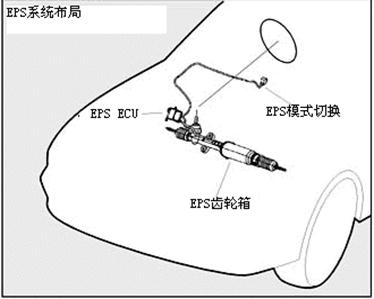
图1
电子动力转向系统的工作原理:
电子动力转向系统是通过一个电动机来驱动动力方向盘液压泵或直接驱动转向联动装置。
电子动力转向的功能由于不依赖于发动机转速,所以能节省能源
电子动力转向系统是这样运行的:
传统的动力方向盘系统使用一条引擎辅助传送带驾驶泵浦,提供操作在动力方向盘齿轮或作动器的一个活塞协助驱动的被加压的流体。在电动液压的控制,一个电子动力方向盘包括一台电动机控制的一个高效率泵浦。由一个电控制器调控泵浦压力和流速来控制泵浦的速度,为不同的驾驶路况的提供转向。 泵浦可以在汽车行驶低速时关闭以提供节能(在当代的世界市场上)
电动控制转向使用电动机通过齿轮齿条机构直接连接以达到转向控制(无泵或液体)。多个电机驱动器和多驱动控制的实现是可能的。一个微处理器控制转向动态和驱动的工作。输入因子包括车速,转向,车轮扭矩,角度位置和转率。
工作运行时的具体细节:

“转向传感器”位于变速箱体的输入轴,提供输入信号。 转向传感器实际上是在一个两位一体的传感器: “扭矩传感器”把转换指点扭矩输入和它的方向成电压信号,同时“自转传感器”转换转动速度和方向成电压信号。 共用一个箱体的“接口”电路把扭矩传感器和自转传感器的信号转换成控制电子电路可处理的信号。从指点传感器的输入由那微处理器的控制单元消化也监测从车速传感器的输入。 传感器输入然后被比较确定多少机械化根据一张被预编程序的“力量地图”需要在控制单元的记忆。 控制单元然后派出适当的命令对然后供给电动机以潮流的“电源装置”。 马达推挤机架在右边或左边根据哪个方式电压流动(扭转潮流扭转方向马达旋转)。 增加潮流对马达增加功率协助。系统有三种操作方式: 左边或右边机械化提供以回应从指点扭矩和自转传感器的输入的输入的“正常”控制方式; 被用于在完成轮以后协助指点回归的“回归”控制方式; 并且改变与车速改进路感受和挫伤佣金的“更加潮湿的”控制方式。如果方向盘被转动,并且举行在充分锁位置和指点协助到达最大值,控制单元使潮流降低到电动机防止也许损坏马达的超载情况。 控制单元也被设计保护马达以防止电压浪涌免受一个有毛病的交流发电机或充电的问题。
电子转向控制单位有能力在自我诊断的缺点通过监测系统输入和产品和电动机的激励电流上。 如果问题发生,控制单元通过开动在电源装置的一个故障自动保险的中转关闭系统。 这消灭所有机械化,造成系统恢复回到手工指点。 破折号EPS警告灯也被阐明警告司机。 要诊断问题,技术员跳服务检查连接器的终端并且读出问题代码。
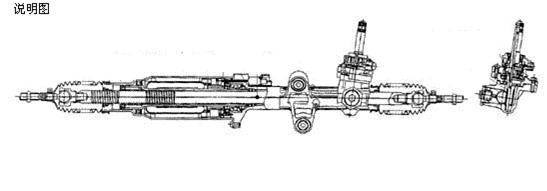
图 2
电子动力方向盘机制
当前发明与提供的供给动力的援助一电子功率驱动器马达关连给车操纵机构。根据当前发明的一个方面,那里为提供供给动力的援助提供一个电子功率驱动器机制给有车的操纵机构一名手动地可旋转的成员为操作操纵机构、传动机构包括可行扭矩的传感器感觉手动地被申请于可旋转的成员的扭矩,一个电子功率驱动器马达操纵着被连接到可旋转的成员和安排控制主驱动电动机自转速度和方向以回应从扭矩传感器收到的信号的控制器,扭矩传感器包括为与可旋转的成员的连接适应的传感器轴形成引伸因此,以便扭矩通过前述传感器轴被传送,当时 可旋转的成员被转动,并且应变仪在导致的信号传感器轴手动地登上表示通过前述轴被传送的相当数量扭矩。
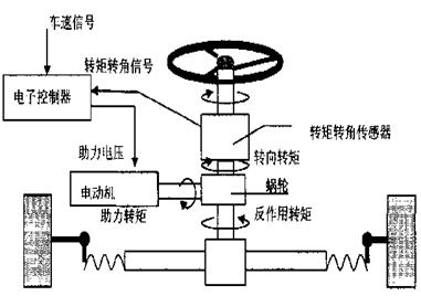
图3
传感器轴不旋转更好地登上在一个轴向末端在第一名联结成员和不旋转地登上在它的相反轴向末端在第二名联结成员,第一和第二名联结成员相互允诺允许有限的自转之间连接,以便在一个被预先决定的极限之下的扭矩由仅传感器轴传送,并且,以便在前述被预先决定的极限之上的扭矩通过第一和第二名联结成员被传送。
更适宜地安排第一和第二名联结成员作为操纵的连接的第一和第二个部分的一座桥梁互相的旋转式成员。合适的传感器轴是通常在多数的长方形横断面它的长度中。应变仪包括一个或更多的适应地看见了谐振器绑到传感器轴上。好的马达操纵的被连接到可旋转的成员通过传动器。马达更好地包括一个工具箱和同心地被安排相对可旋转的成员。当前发明的Various方面此后将描述,关于伴随的图画, :图1是一个车操纵机构的一个图表看法包括一个电子功率驱动器机制根据当前发明,图 2是说明在图显示的传动机构的各种各样的组分的之间流程图互作用1上,图 3是一个轴截面通过在图显示的传动机构1,图4上是一张截面图被采取沿着线IV-IV在表3,图5是在图显示的输入推进联结的一张更加详细的分解图3上,和图 6是显示在表3.的传动器的一张更加详细的分解图。 图1的最初Referring,那里显示一个车操纵机构10操纵的被连接到一个对易操纵的路轮子12。这个显示的操纵机构包括一个齿条和齿轮汇编14被连接到路轮子12通过联接15。 鸟翼末端(没显示)汇编14可旋转地驾驶一名手动地可旋转的成员以驾驶杆18的形式哪些由方向盘19手动地转动。这个驾驶杆18包括包括一台电主驱动电动机的一个电力的传动机构30 (没显示在驾驶的鸟翼末端图1)上以回应在驾驶杆18的扭矩装货为了为机械人员提供力量援助,当转动方向盘19时。如概要地被说明在表2,电力的传动机构包括测量驾驶杆申请的扭矩18,当驾驶鸟翼末端时并且提供信号给控制器40的扭矩传感器20。 控制器40被连接到主驱动电动机50并且控制电流被提供给马达50控制马达50和它的自转的方向扭矩引起的相当数量。马达50 操纵的更适宜地被连接到驾驶杆18通过工具箱60,更适宜地一个周转齿轮箱子和传动器70。 在一定条件下传动器70在正常运行时更适宜地永久地接合并且是有效的隔绝从马达50的驱动使鸟翼末端通过传动机构30手动地被驾驶。 这是使机制的安全特点起作用在试图的马达50情形下驾驶太快速的驾驶杆并且/或者在错误的方向或在案件 电动机和工具箱占领了。
扭矩传感器20更适宜地是一个汇编包括在扭矩应用达到的传感器轴登上应变仪能够准确测量张力在一个被预先决定的范围之内的一个短的传感器轴。被测量扭矩的被预先决定的范围是0-lONm; 更好是关于l-5Nm。被测量的扭矩的范围更好地对应于大约0-1000微指令,并且传感器轴的建筑更好被选择这样5Nm扭矩比在轴的2°导致较少的转弯,少于1 °。好的应变仪是锯谐振器,在WO91/13832被描述的一台适当的锯谐振器。 类似在图显示的那WO91/13832 3上更好地运用配置,二看见谐振器被安排在对轴轴的45°和在90°对互相。谐振器经营与在200-400 MHz之间共鸣频率和被安排导致信号到控制器1 MHz 40 ± 500 KHz根据传感器轴的自转方向的自我调节。 因此,当传感器轴不被扭转的归结于缺乏扭矩时,它导致一个1 MHz信号。当它导致在1.0到1.5 MHz之间的一个信号的传感器轴在一个方向被扭转。 当传感器轴在相反方向时被扭转它导致在1.0到0.5 MHz之间的一个信号。 因而同样传感器能导致信号表示程度扭矩并且传感器轴的自转的方向。好的马达扭矩引起的相当数量以回应在0-10Nm之间被测量的扭矩是0-40Nm,并且为在l-5Nm之间被测量的扭矩是0-25Nm。反馈电路提供自我调节,借以马达使用的电流由控制器40测量并且比较保证马达在正确方向运行并且提供期望功率协助。 控制器更好地行动使被测量的扭矩降低到零和如此控制马达增加它的扭矩产品减少被测量的扭矩。 (没显示)更适宜地提供车速传感器哪些寄发一个信号表示车速到控制器。 控制器使用这个信号修改程度力量协助提供以回应被测量的扭矩。将提供在低车速最大力量协助的,因而,并且将提供高车速极小的力量协助。更适宜地是逻辑顺序器有一个现场可编程序的门数组例如XC 4005如Xilinx供应这个控制器。 这样控制器不依靠软件和,因此能更起作用可靠地在汽车车环境里。 被想象也许使用有逻辑的序列一个现场可编程序的列阵。 一个电力传动机构10的A具体建筑在表3.被说明。
电子动力转向系统(英文简称EPS), 与液压动力转向系统(HPS)相比,EPS具有很多优点。即EPS的优势在于:
1)效率高。HPS效率很低,一般为60%~70%;而EPS与电机连接,效率高,有的可高达90%以上。
2)耗能少。汽车在实际行驶过程中,处于转向的时间约占行驶时间的5%,对于HPS系统,发动机运转时,油泵始终处于工作状态,油液一直在管路中循环,从而使汽车燃油消耗率增加4%~6%;而EPS仅在需要时供能,使汽车的燃油消耗率仅增加0.5%左右。
3)“路感“好。由于EPS内部采用刚性连接,系统的滞后特性可以通过软件加以控制,且可以根据驾驶员的操作习惯进行调整。
4)回正性好。EPS结构简单内部阻力小,回正性好,从而可得到最佳的转向回正特性,改善汽车操纵稳定性。
5)对环境污染少。HPS液压回路中有液压软管和接头,存在油液泄露问题,而且液压软管不可回收,对环境有有一定污染;而EPS对环境几乎没有污染。
6)可以独立于发动机工作。EPS以电池为动力元件,只要电池电量充足,不论发动机出于何种状态,都可以产生助力作用。
7)应有范围广。
8)装配性好易于布置。
现在,动力转向系统已成为一些轿车的标准设置,全世界约有一半的轿车采用动力转向。随着汽车电子技术的发展,目前一些轿车已经使用电动助力转向器,使汽车的经济性、动力性和机动性都有所提高。电动助力转向装置是汽车上一种新的助力转向系统装置,近年来在国内外发展迅速,由于它采用了可编程电子控制装置,在带来灵活性的同时也存在着安全隐患.在分析这种产品特殊性的基础上,笔者结合电子控制装置的特点,指出了事关安全性的因素,提出了处理安全性的措施,并讨论了几个事关安全性的具体问题.研究结果表明:现有标准不能够满足电动助力转向装置安全性的需要;并提出了对电动助力转向装置进行安全性测评的思想.研究工作对电动助力转向装置的开发以及评价具有参考意义。