题目:数据记录仪 毕业设计附件 —总体方案设计,及显示电路、软件
姓 名:
学 号:
学 院:
专 业:
指 导 教 师:
协助指导教师:
20xx年8月7日
目 录
毕业设计任务书 ............................................................................................... 1
毕业设计开题报告 ........................................................................................... 2
毕业设计外文原文及译文 ............................................................................... 6
毕业设计程序清单 ......................................................................................... 15
大学毕业设计(论文)任务书
题目: 数据记录仪—总体方案设计及显示电路、软件 专业: 指导教师:
学院: 学号:班级: 姓名:
一、主要内容和基本要求
设计数据记录仪总体方案、制定各个子系统之间的接口(包括硬件及软件),并设计显示部分的硬件电路及软件程序。应包括如下功能:
1. 可以对至少3路模拟量进行采集。
2. 数据采集的时间间隔可调。
3. 能够适应不同的模拟量形式(0-5V及4-20mA)以及不同的物理量(温度、压力、流量)和量程。
4. 采集的数据通过USB口存入U盘。
5. 具有无线传输功能,采集的数据可以通过无线模块传输给上位计算机(PC机)。
二、主要参考资料
[1]胡健.单片机原理及接口技术[M].北京:机械工业出版社,2004.10
[2]郭俊杰.基于USB接口的多通道数据采集仪设计[J].兵工自动化,2007.2(26)
[3]陈天如.计算机网络与通信[J].电气自动化,2006.3(28)
[4]金瓯帆.单片机模拟串口的设计[D].电子世界,2005(2)
[5]张友德.单片微型机原理、应用和实验[M].上海:复旦大学出版社,2008-01-01
三、进度要求
1周:完成开题报告
2-4周:完成基本电路设计
5-10周:调试、修改
11-12周:英文翻译及论文
13周:论文修改装订,准备答辩
14周:答辩
-1-
大学毕业设计开题报告
题目:
专业: 指导教师:
学院: 学号:班级: 姓名:
一、课题任务与目的
课题任务:利用单片机技术,无线数传技术,U盘存储技术,数/模转换技术完成一个多通道数据记录仪。
课题目的:设计并完成一个新型数据记录仪,选用一种数据存储器从而实现数据记录仪拥有大容量的存储空间支持长时间连续的数据采集。数据以txt格式存储在U盘中,易于在PC机上对数据进行查看,转存,分析。
二、调研资料情况 数据记录仪的发展
数据记录仪是一种从传感器获取测量结果,并将这些结果进行存储的电子仪器。在最简单的形式中,技术人员将烤箱的温度记录在一张纸上就是数据记录。随着技术的发展,通过电子设备,这个过程已经得到简化和变得比较精确、多用途和可靠。设备从简单的存储器发展到复杂的电脑系统。数据采集技术在过去40到50年以来已经取得了很大的飞跃。举例来说,在 50 年以前,在一个著名的学院实验室中,为追踪用青铜做的坩埚中的温度上升情况的装置是由热电偶、继电器、查询台、一捆纸和一支铅笔。随着科学技术的发展,数据记录仪也从一根铅笔和一张纸,发展到长图表记录仪,再到可以使用液晶显示器的显示数据和图形的数据记录仪,经历了从手工到仪表,从有纸,到无纸的一个发展的过程。采集速度也从最初的人工只能监测几个采集点,到现在每秒可以采集20万个点的数据;存储空间也在不断的提升。
1铅笔和纸
用铅笔和纸的方式历史悠久,而且它便宜、易获得、快速和容易开始。而你所需要的就是捕捉到数字信息,然后开始用手记录数据。不幸的是这种方法容易发生错误、采集速度很慢和需要太多的人工分析。此外,它只能单通道采集数据。 2长条图表记录仪
现代多种版本的长条图表记录仪允许你从多个输入取得数据。他们提供数据的长备纸记录,因为数据是图解的格式,他们易于现场采集数据。一旦建立了长条图表记录
-2-
仪,在没有操作员或计算机的情况下,数记录仪能够自行运转。缺点是缺乏灵活性和精度低,时常限制在百分点。除此之外,它们的应用受到了限制。举例来说,他们不能够与另外的装置轮流工作。还有就是笔和纸的维护,纸的供给和数据的存储,最重要的是纸的滥用和浪费。但是记录仪相当容易建立和操作,为数据快速而简单的分析提供永久的记录。
3 PC机插件卡片
PC机插件卡片是单板测量系统,它利用ISA或PCI总线在PC机内扩大插槽。它们时常具有高达每秒1000点的阅读速率。一般是8到16个采集通道,采集的数据直接存储在电脑里,然后进行分析。因为卡片本质上是计算机的一部分,建立测试是容易的。缺点,PC机插件卡片时常只有12字的容量,容量太小。此外,PC机内的电子环境很容易发出噪声、产生高速率的时钟和总线噪声,电子接触面限制PC机插件卡片的精度。同时为了测量一些非电量输入信号,如压力、温度和阻力,需要一些外部信号监测的器件。
4数据电子自动记录仪
数据电子自动记录仪是典型的单机仪器,一旦配备它们, 就能测量、记录和显示数据而不需要操作员或计算机参与。它们能够处理多信号输入,有时可达120通道。 精度可与台式 DMM 相匹敌,由于它在22字、0.004个百分率的精度范围内运转。一些数据电子自动记录仪有能力按比例测量。使用数据电子自动记录仪的一个好处就是他们的内部监测信号。大部分能够直接地测量若干不同的输入信号,而不需要额外的信号监测器件。一个通道能够监测热电偶、温阻器(RTD)和电压。
与PC机连接容易将数据传送到电脑进行进一步的分析。大多数数据电子自动记录仪可设计为柔性和简单的组态和操作,而且经由电池包裹或其它方法,多数提供远程位置的操作选项。
4前端数据采集
前端数据采集经常做成模块而且是典型地与PC机或控制器连接。他们被用于自动化的测试中,为其它测试装备采集数据、控制和循环检测信号。发送信号测试装备的零配件。前端运转的效率是非常高的,能与速度和精度与最好的单机仪器匹敌。前端数据采集在很多模型里都能运行,包括VXI版本,如Agilent E1419A 多功能测量和VXI控制模型,虽然前端器成本已经降低,但是这些系统依然会非常贵,除非你需要提供高的运转能力.
近些年随着数据采集系统的广泛应用,人们对数据记录仪的主要技术指标,如采样频率、分辨率、精度、控制方式、抗干扰能力、数据存储容量及数据传输方式等方面都提出了越来越高的要求。数据记录仪也从最早的单一通道的数据采集,发展到多条采集通道,可采集多种参量,如温度、压力、电流、速度、张力、位移等;可输入
-3-
多种信号,如标准电流、标准电压、频率信号等。采样频率由低速向到高速迅速发展,目前可达20万个点/秒。多种的储存介质可供选择,存储容量也越来越大。可以通过各种无线传输技术向外传输数据。通道间隔离,抗干扰能力强,能在恶劣的环境下工作。
数据记录仪的现状
根据对数据记录仪的发展的研究,不难发现随着科学技术的不断发展,用于工控现场的嵌入式计算机的数据采集系统,由于工业现场环境的复杂性和多样性,对数据采集系统的硬件和软件设计提出了更高的要求,小型化、易便携,数据易转移,具有较高的抗震动冲击能力,兼容性和散热性好,高可靠性和可维护性等。尤其是为满足航空、航天、遥感技术的发展和应用需求,数据记录仪向着超高速、超大储存容量方面发展。出现了瞬态记录的概念,超大容量的数据储存空间已达1TB。
但是在另外的一些领域与行业中,例如煤矿里面瓦斯浓度的检测,酒厂酿酒罐的温度检测;药品仓库、制药行业、资料档案室温湿度的记录;冷库、冷藏车、食品生产储藏及化工反应釜的温度记录;水压自动记录;管道压力记录等等。这些参量随时间变化缓慢,测量精度要求不高,但检测过程漫长,记录数据可长达数月,甚至整年,即要求数据记录仪具有超大的存储容量。针对这种市场需求,分析目前市场上的低速数据记录仪,存储容量小(一般在MB级),数据多以HXE格式直接储存,不便于PC机查看和分析,用户查看数据时需要通过专用软件对数据进行相应的处理后才能查看,价格昂贵等问题。
参考资料:
[1]韩茜.罗丰.吴顺君高速大容量固态存储系统的设计[J]-雷达科学与技术2005(2)
[2]沈沛,戈福庆. 浅淡记录仪的发展趋势[J]. 中国仪器仪表, 1998, (04)
[3]金建祥,杨颖,郭豪杰,李杰. 无纸记录仪──记录仪发展新趋势[J]. 工业仪表与自动化装置, 1995, (04)
三、初步设计方法与实施方案
用户通过键盘和显示器设定系统时钟,选择所要启动的记录通道,设定该通道的数据量程,采集频率和采集次数。然后启动该通道的数据记录。本数据采集仪,会根据用户设定的记录参数,进行定时记录。设定时间到时,记录仪将对应通道口的模拟量数据进行A/D转换后,将所转化后所得的数字量数据根据用户输入的该通道量程进行相应的计算。得到对应当前数字量的实际物理值。将此物理值,通道标号,转换的具体时间、日期转换成相应的ASCII码发送到U盘中,并以txt格式储存。转换后的数据将被保存到相应的文件中。
-4-
本数据采集仪配有无线数传系统。在上位机上,通过软件发送命令,可以随时将已采集的数据传送到上位机上。
1更改储存方法
现在的数据记录仪对数据的记录多储存于数据记录仪的内存中,数据的查看很不方便,需要通过特殊软件将数据传输到计算机中。而且其数据储存空间为固定的,这样采集的数据量也受到了限制。
所以,将对数据的储存方法进行更改。采用U盘作为存储器,U盘的好处在于其容量可变,不同大小的U盘所能储存的数据量不同。当一个U盘存储满了以后,只需要更换一个U盘就可以继续进行数据的记录。
数据是以txt格式储存到U盘中,查看数据十分的方便,拔下U盘插到任何一台计算机中就可以查看数据,对数据进行分析。
经过此改进,可使数据记录仪使用更加人性化,使用起来更加的方便。
2降低成本
此次所设计的数据记录仪,采用单片机技术为核心技术,作为整个系统的中枢控制器,降低了一部分的制造成本。
由于储存方式的改变,储存介由扩展内存改为U盘存储,降低了存储介质的成本。目前,基于USB2.0接口的移动存储设备已经被广泛使用,尤其是采用USB-FLASH技术的U盘产品的容量由几年前的16M增加到现在的4G以上。U盘通常是作为计算机的外部存储设备,其造价也相对低廉,适用范围广阔。
四、预期结果
预期结果是完成一个具有多路数据采集的数据记录仪,拥有至少三路的模拟量通道,可接受0-5v或4-20mA 的信号输入,并将数据进行数模转换后以txt格式储存到U盘中。 系统中带有无线接收发送装置,可通过上位机对整个仪器进行监控,通过无线传输方式将数据传送至上位pc机。
五、进度计划
1周:完成开题报告
2-4周:完成基本电路设计
5-10周:调试、修改
11-12周:英文翻译及论文
13周:论文修改装订,准备答辩
14周:答辩
-5-
大学毕业设计(论文)外文原文及译文
专业: 指导教师:
学院: 学号:班级: 姓名: 题目:数据记录仪—总体方案设计及显示电路、软件
一、 外文原文
出处:/developers/docs/
Protocol Layer
1.1 Byte/Bit Ordering
Bits are sent out onto the bus least-significant bit (LSb) first, followed by the next LSb, through to the mostsignificant bit (MSb) last. In the following diagrams, packets are displayed such that both individual bits and fields are represented (in a left to right reading order) as they would move across the bus.
Multiple byte fields in standard descriptors, requests, and responses are interpreted as and moved over the bus in little-endian order, i.e., LSB to MSB.
1.2 SYNC Field
All packets begin with a synchronization (SYNC) field, which is a coded sequence that generates a maximum edge transition density. It is used by the input circuitry to align incoming data with the local clock. A SYNC from an initial transmitter is defined to be eight bits in length for full/low-speed and 32 bits for high-speed. Received SYNC fields may be shorter as described in Chapter 7. SYNC serves only as a synchronization mechanism and is not shown in the following packet diagrams. The last two bits in the SYNC field are a marker that is used to identify the end of the SYNC field and, by inference, the start of the PID.
1.3 Packet Field Formats
Field formats for the token, data, and handshake packets are described in the following section. Packet bit definitions are displayed in unencoded data format. The effects of NRZI coding and bit stuffing have been removed for the sake of clarity. All packets have distinct Start- and End-of-Packet delimiters. The Start-of- Packet (SOP) delimiter is part of the SYNC field.
1.4 Token Packets
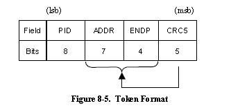
Figure 8-5 shows the field formats for a token packet. A token consists of a PID,
-6-
specifying either IN, OUT, or SETUP packet type and ADDR and ENDP fields. The PING special token packet also has the same fields as a token packet. For OUT and SETUP transactions, the address and endpoint fields uniquely identify the endpoint that will receive the subsequent Data packet. For IN transactions, these fields uniquely identify which endpoint should transmit a Data packet. For PING transactions, these fields uniquely identify which endpoint will respond with a handshake packet. Only the host can issue token packets. An IN PID defines a Data transaction from a function to the host. OUT and SETUP PIDs define Data transactions from the host to a function. A PING PID defines a handshake transaction from the function to the host.
Token packets have a five-bit CRC that covers the address and endpoint fields as shown above. The CRC does not cover the PID, which has its own check field. Token and SOF packets are delimited by an EOP after three bytes of packet field data. If a packet decodes as an otherwise valid token or SOF but does not terminate with an EOP after three bytes, it must be considered invalid and ignored by the receiver.
1.4.1 Start-of-Frame Packets
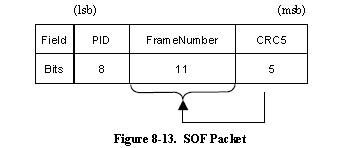
Start-of-Frame (SOF) packets are issued by the host at a nominal rate of once every 1.00 ms 0.0005 ms for,a full-speed bus and 125 μs 0.0625 μs for a high-speed bus. SOF packets consist of a PID indicating packet type followed by an 11-bit frame number field as illustrated in Figure 8-13.
The SOF token comprises the token-only transaction that distributes an SOF marker
and accompanying frame number at precisely timed intervals corresponding to the start of
-7-
each frame. All high-speed and fullspeed functions, including hubs, receive the SOF packet. The SOF token does not cause any receiving function to generate a return packet; therefore, SOF delivery to any given function cannot be guaranteed.
The SOF packet delivers two pieces of timing information. A function is informed that an SOF has occurred when it detects the SOF PID. Frame timing sensitive functions, that do not need to keep track of frame number (e.g., a full-speed operating hub), need only decode the SOF PID; they can ignore the frame number and its CRC. If a function needs to track frame number, it must comprehend both the PID and the time stamp. Full-speed devices that have no particular need for bus timing information may ignore the SOF packet.
1.4.2 Handshake Packets
Handshake packets are used to report the status of a data transaction and can return values indicating successful reception of data, command acceptance or rejection, flow control, and halt conditions. Only transaction types that support flow control can return handshakes. Handshakes are always returned in the handshake phase of a transaction and may be returned, instead of data, in the data phase. Handshake packets are delimited by an EOP after one byte of packet field. If a packet decodes as an otherwise valid handshake but does not terminate with an EOP after one byte, it must be considered invalid and ignored by the receiver. There are four types of handshake packets and one special handshake packet:
1.ACK indicates that the data packet was received without bit stuff or CRC errors over the data field and that the data PID was received correctly. ACK may be issued either when sequence bits match and the receiver can accept data or when sequence bits mismatch and the sender and receiver must resynchronize to each other. An ACK handshake is applicable only in transactions in which data has been transmitted and where a handshake is expected. ACK can be returned by the host for IN transactions and by a function for OUT, SETUP, or PING transactions.
2.NAK indicates that a function was unable to accept data from the host (OUT) or that a function has no data to transmit to the host (IN). NAK can only be returned by functions in the data phase of IN transactions or the handshake phase of OUT or PING transactions. The host can never issue NAK. NAK is used for flow control purposes to indicate that a function is temporarily unable to transmit or receive data, but will eventually be able to do so without need of host intervention.
3.STALL is returned by a function in response to an IN token or after the data phase
-8-
of an OUT or in response to a PING transaction. STALL indicates that a function is unable to transmit or receive data, or that a control pipe request is not supported. The state of a function after returning a STALL (for any endpoint except the default endpoint) is undefined. The host is not permitted to return a STALL under any condition.
The STALL handshake is used by a device in one of two distinct occasions. The first case, known as “functional stall,” is when the Halt feature associated with the endpoint is set. A special case of the functional stall is the “commanded stall.” Once a function?s endpoint is halted, the function must continue returning STALL until the condition causing the halt has been cleared through host intervention.
Protocol stall is unique to control pipes. Protocol stall differs from functional stall in meaning and duration. A protocol STALL is returned during the Data or Status stage of a control transfer, and the STALL condition terminates at the beginning of the next control transfer (Setup). The remainder of this section refers to the general case of a functional stall.
2 Transaction Packet Sequences
The packets that comprise a transaction varies depending on the endpoint type. There are four endpoint types: bulk, control, interrupt, and isochronous.
Batch transaction type were characterized by the error detection and retry way to ensure the host and function of data between the components of the ability to send error-free. Flow control and hang in some conditions, the data phase handshake signals are replaced, resulting in two with no data transfer phase of the transaction.
When the host is ready to receive a batch of data when it sends the input tag. Feature port through the return packet, or if unable to return data, NAK, or STALL handshake is returned as a response. NAK means the feature is temporarily unable to return data, and STALL be stopped permanently, said the port needs to USB system software intervention. If the host receives a legitimate data packets, then it uses ACK handshake to answer. If you receive data with the host detects an error, then it does not return handshake contracted out features. Control of transmission at least two transaction stages: the establishment and status. Transmission can be selectively controlled, including the establishment and status data between the stages of phase. In the establishment phase, the establishment of services for the features of the control port to transmit information. Establishment of issues in the format similar to the output, but the use of the building rather than the output of the PID. Building is always in the establishment of services relative to the use of data DATA0 PID.
-9-
Before the establishment of the functional components must accept the establishment of data and use ACK response, if the data is damaged, then discards the data and do not return to shake hands.
Control the data transmission phase, if any, by more than one input or output transaction structure, compliance and batch send the same protocol rules. All the data phase of the transaction must have the same direction (that is, all input or all output). In the data phase, the amount of data to be sent, and its direction is specified in the establishment phase. If the amount of data exceeds the previously identified data packet size, the data in support of the largest packet size of the number of transactions to be sent (input or output). Any remaining data as a residual in the final transaction is sent.
Control of the state of transmission phase is the last one operation sequence. State phase at a relatively earlier stage of the data to characterize the changes in flow direction, and always use the DATA1 PID. For example, if the data phase transaction constituted by the output, the state is a single input transaction. If the control sequence is no data transmission phase, then it is by the establishment phase and the subsequent transaction by the input stages, consisting of the state.
Interrupt transactions may consist of IN or OUT transfers. Upon receipt of an IN token, a function may return data, NAK, or STALL. If the endpoint has no new interrupt information to return (i.e., no interrupt is pending), the function returns a NAK handshake during the data phase. If the Halt feature is set for the interrupt endpoint, the function will return a STALL handshake. If an interrupt is pending, the function returns the interrupt information as a data packet. The host, in response to receipt of the data packet, issues either an ACK handshake if data was received error-free or returns no handshake if the data packet was received corrupted. Such endpoints use multiple transactions in a microframe as defined in that section. Each transaction for a highbandwidth.
When an endpoint is using the interrupt transfer mechanism for actual interrupt data, the data toggle protocol must be followed. This allows the function to know that the data has been received by the host and the event condition may be cleared. This “guaranteed” delivery of events allows the function to only send the interrupt information until it has been received by the host rather than having to send the interrupt data every time the function is polled and until the USB System Software clears the interrupt condition.
3 Data Toggle Synchronization and Retry
The USB provides a mechanism to guarantee data sequence synchronization between data transmitter and receiver across multiple transactions. This mechanism provides a
-10-
means of guaranteeing that the handshake phase of a transaction was interpreted correctly by both the transmitter and receiver. Synchronization is achieved via use of the DATA0 and DATA1 PIDs and separate data toggle sequence bits for the data transmitter and receiver. Only in the receiver can receive data and with the correct data PID received error-free packet when the receiver sequence bit before switching. But only in the data transmitter to receive a legitimate ACK handshake when the transmitter sequence bit before switching. Data transmitter and receiver must be synchronized in the transaction the beginning of the timing of their position. Synchronization mechanism used varies with the transaction type. ISO does not support data transmission switch synchronization.
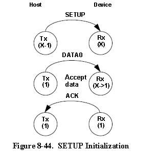
Control transfers use the SETUP token for initializing host and function sequence bits. Figure 8-44 shows the host issuing a SETUP packet to a function followed by an OUT transaction. The numbers in the circles represent the transmitter and receiver sequence bits. The function must accept the data and return ACK. When the function accepts the transaction, it must set its sequence bit so that both the host?s and function?s sequence bits are equal to one at the end of the SETUP transaction.
If data cannot be accepted or the received data packet is corrupted, the receiver will issue a NAK or STALL handshake, or timeout, depending on the circumstances, and the receiver will not toggle its sequence bit. Any non-ACK handshake or timeout will generate similar retry behavior. The transmitter, having not received an ACK handshake, will not toggle its sequence bit. As a result, a failed data packet transaction leaves the transmitter?s and receiver?s sequence bits synchronized and untoggled. The transaction will then be
-11-
retried and, if successful, will cause both transmitter and receiver sequence bits to toggle.
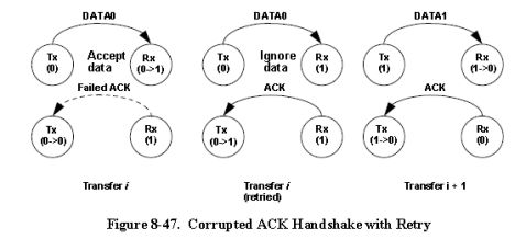
The transmitter is the last and only agent to know for sure whether a transaction has been successful, due to its receiving an ACK handshake. A lost or corrupted ACK handshake can lead to a temporary loss of synchronization between transmitter and receiver as shown in Figure 8-47. Here the transmitter issues a valid data packet, which is successfully acquired by the receiver; however, the ACK handshake is corrupted.
At the end of transaction i, there is a temporary loss of coherency between transmitter and receiver, as evidenced by the mismatch between their respective sequence bits. The receiver has received good data, but the transmitter does not know whether it has successfully sent data. On the next transaction, the transmitter will resend the previous data using the previous DATA0 PID. The receiver?s sequence bit and the data PID will not match, so the receiver knows that it has previously accepted this data. Consequently, it discards the incoming data packet and does not toggle its sequence bit. The receiver then issues ACK, which causes the transmitter to regard the retried transaction as successful. Receipt of ACK causes the transmitter to toggle its sequence bit. At the beginning of transaction i+1, the sequence bits have toggled and are again synchronized.
The data transmitter must guarantee that any retried data packet is identical (same length and content) as that sent in the original transaction. If the data transmitter is unable, because of problems such as a buffer underrun condition, to transmit the identical amount of data as was in the original data packet, it must abortthe transaction by generating a bit stuffing violation for full-/low-speed. An error for high-speed must be forced by taking the currently calculated CRC and complementing it before transmitting it. This causes a detectable error at the receiver and guarantees that a partial packet will not be interpreted as a good packet. The transmitter should not try to force an error at the receiver by sending
-12-
a constant known bad CRC. A combination of a bad packet with a “bad” CRC may be interpreted by the receiver as a good packet.
4 Error Detection and Recovery
The USB permits reliable end-to-end communication in the presence of errors on the physical signaling layer. This includes the ability to reliably detect the vast majority of possible errors and to recover from errors on a transaction-type basis. Control transactions, for example, require a high degree of data reliability; they support end-to-end data integrity using error detection and retry. Isochronous transactions, by virtue of their bandwidth and latency requirements, do not permit retries and must tolerate a higher incidence of uncorrected errors.
Neither the device nor the host will send an indication that a received packet had an error. This absence of positive acknowledgement is considered to be the indication that there was an error. As a consequence of this method of error reporting, the host and USB function need to keep track of how much time has elapsed from when the transmitter completes sending a packet until it begins to receive a response packet. This time is referred to as the bus turn-around time. Devices and hosts require turn-around timers to measure this time. For full-/low-speed transactions, the timer starts counting on the SE0-to-?J? transition of the EOP strobe and stops counting when the Idle-to-?K? SOP transition is detected. For high-speed transactions, the timer starts counting when the data lines return to the squelch level and stops counting when the data lines leave the squelch level. The device bus turn-around time is defined by the worst case round trip delay plus the maximum device response delay. If a response is not received within this worst case timeout, then the transmitter considers that the packet transmission has failed. Timeout is used and interpreted as a transaction error condition for many transfer types. If the host wishes to indicate an error condition for a transaction via a timeout, it must wait the full bus turn-around time before issuing the next token to ensure that all downstream devices have timed out.
False EOPs must be handled in a manner which guarantees that the packet currently in progress completes before the host or any other device attempts to transmit a new packet. If such an event were to occur, it would constitute a bus collision and have the ability to corrupt up to two consecutive transactions. Detection of false EOP relies upon the fact that a packet into which a false EOP has been inserted will appear as a truncated packet with a CRC failure. (The last 16 bits of the data packet will have a very low probability of appearing to be a correct CRC.)
-13-
The host and devices handle false EOP situations differently. When a device receives a corrupted data packet, it issues no response and waits for the host to send the next token. This scheme guarantees that the device will not attempt to return a handshake while the host may still be transmitting a data packet. If a false EOP has occurred, the host data packet will eventually end, and the device will be able to detect the next token. If a device issues a data packet that gets corrupted with a false EOP, the host will ignore the packet and not issue the handshake. The device, expecting to see a handshake from the host, will timeout the transaction.
If the host receives a corrupted full-/low-speed data packet, it assumes that a false EOP may have occurred and waits for 16 bit times to see if there is any subsequent upstream traffic. If no bus transitions are detected within the 16 bit interval and the bus remains in the Idle state, the host may issue the next token.
-14-
二、译文
协议层
1.1位排序
当数据位被发送到总线的时,首先发送的是最低有效位,跟着发送的是下一个最低有效位,最后发送的是最重要的有效位。在后来的图表中,数据包是以下列形式显示的,即有单个的位,也有字段(从左到右的阅读顺序)作为他们通过总线的顺序。在解释,要求和回馈中出现的多重字节部分会被翻译成可以进行跳跃的小型命令字符串。例如说,由LSB转换成MSB
1.2同步字段
所有的数据包由一个同步的可以启动最大边界传输密度的编码片段开始。这是用来使电路的输入数据可以与本地数据同步。第一个传输器的同步设置定义为一个高速/低速的8位数据,和一个告诉的32位数据。收到的同步信息可以简单描述为第7章所述。信息同步只为同步机械和没有显示下列数据图表的装置服务。在同步设置中,最后两个字节为定义同步区域的结束,或者相反地,也可以定义起始。
1.3数据包字段格式
令牌的字段格式,数据和握手包将被描述在后面的章节中。包位的定义是以未编码的数据格式显示出的。为了更加的清楚,移除了NRZI编码和位填充的影响。所有的数据包都有明显的包的启动和结束分隔符。包的启动分隔符是同步字段的一部分。
1.4标记数据包
图8-5显示了标记包的字段格式。一个标记包由PID,(指定了包的类型是输入,输出还是建立类型),ADDR和ENDP组成,特殊的标记包PING作为一个标记包也有相同的字段。对于输出和建立事务,地址和端口字段唯一地确定了接下来将收到数据包的端口。对于输入事务的,这些字段唯一地确定了哪个端口应该传送数据包。只有主机能发出标记包。对于PING事务的,这些字段唯一标示了哪个端口将回应一个握手数据包。只有主机可以发送标记包。输入PID定义了一个数据事物是从功能部件到主机的。输出和建立PID定义了从主机到功能部件的数据事务。PING PID定义了握手数据的事务从功能部件到主机。
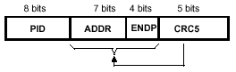
图8-5 标记包格式
如上图所示,标记包由5位CRC组成包括覆盖地址和端口字段。CRC并不覆盖PID,
-15-
因为它有自己的核对字段。标记和帧开始(SOF)包是被由3个字节的包字段数据后面包结束分割开的。如果包被解码为一个本来有效的标记或SOF,但却没有以EOP终止在3个字节后,则它必须被视为无效的,并被接收器忽略。
1.4.1 帧开始包
帧开始包是由主机按额定速率发出的,对于全速总线,以每1.00 ms ±0.0005 ms发出一个。对于高速总线以每125μs±0.0625 μs一次的速度发出。帧开始包是由指示包类型的PID和其后的11位的帧号字段组成,如图8-6中所示。
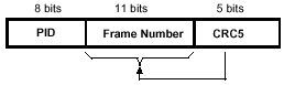
图8-6 帧开始包
帧开始包标记组成了仅有标记的事务,它以相对于每帧的开始精确计算的时间间隔发送帧开始记号和伴随的帧数。包括集线器的所有高速功能部件和全速功能部件都可收到帧开始包。SOF标记不会造成任何接收功能部件产生返回包;因此,不能保证向任何给定的功能部件发送的SOF都能被收到。
SOF包发送2个时间调配信息。功能部件已经被告知发生SOF,当它检测到一个SOF的PID的时候。对帧时间敏感而没必要追踪帧数(例如集线器)的功能部件,仅需对SOF的PID译码 ;可忽略帧数和其CRC。如果功能部件需要追踪帧数,它必须对PID和时间戳都进行译码。全速设备不被总线时间调配信息的没有特别需要,可以忽略SOF包。
1.4.2 握手包
交互数据包用于对数据交换的情况进行报告,并且可以反馈成功接收数据的参数值,命令的接受和拒绝情况,数据流的控制和缓冲情况。只有支持流量控制的交换类型可以进行信息交互。交互信息可以反馈信息交换的交互向量,也可以以数据向量的形式代替数据来进行反馈。在传输一个字节的数据包后,交互数据包可以无限的以EOP的形式传输。如果一个数据包解码后是一个逆向可激活的形式,同时没有以一个字节的EOP作为结束,它会被认为无效并被接收器忽略。现在一共有四种交互信息包和一种特殊的交互信息包
1)ACK表示数据包被接收没有位填充或者在数据段的CRC(循环冗余码校验)存在错误,并且没有收到正确的数据PID。ACK在下列的情况下被发布,当时序位匹配且接收器能接受数据的时候,或者当时序位不匹配,但发送方和接收器彼此必须重新同步的时候。ACK握手信号只在数据被传送并且期待握手信号时适用。ACK可由主机返回,而对于输出,建立或者PING事务则由功能部件返回;
-16-
2)NAK表示功能部件不能通过主机接受数据(对于输出事务),或者功能部件没有传输数据到主机(对于输入事务)。NAK仅在功能部件的输入事务的数据时相返回,或在输出事务的握手时相返回。主机不能发送NAK。NAK用于流控制的目的是,表示功能部件暂时不能发送或接收数据,但是最终还是能够在不需主机干涉的情况下发送或接收数据;
3)STALL被一个功能部件送回作为一个输入标记的回应。在输出事务的数据时相之后或者对一个PING事务做出回应,由功能部件返回。STALL表示功能部件不能发送或接收数据,或者一个控制管道请求不被支持。一些在回复STALL后的功能是不明确的(默认端点除外)。在任何情况下都不允许主机返回STALL。
在两个不同场合的一个设备中使用STALL握手。第一种情况,是当挂起特征与端口有联系时所设置的,称为“功能STALL ”。功能STALL的特殊功能是“命令STALL”。如果一个功能部件的端口被挂起,那么功能部件必须继续返回STALL,直到挂起通过主机干涉被清除。
协议STALL是唯一的控制管道。协议STALL和功能STALL在意义和持续时间上是不同。协议STALL在控制传送的数据或状态阶段被返回,并且,STALL条件终止在下一个控制传送的开始终止(建立事务)。这节的剩下的部分将提到功能STALL的一般情况。
2 事务格式
数据包的事务取决于端口的类型。端口类型有4种:批处理,控制,中断和同步。 批处理事务类型的特点是以错误检测和重试的方式保证主机和功能部件之间的数据的无错发送的能力。在某些流控制和挂起条件下,数据时相被握手信号替换,从而产生了没有数据传输的两相的事务。
当主机准备好了接收批处理数据的时候,它发出输入标签。功能部件端口通过返回数据包,或者如果不能返回数据包,则返回NAK或STALL握手作为应答。NAK表示功能部件暂时不能返回数据,而STALL表示端口永久地被停止,指出此端口需要USB系统进行软件干涉。如果主机收到合法的的数据包,则它使用ACK握手数据包作为应答。如果你收数据时主机检测到错误,它将不返回握手数据包,并判断功能部件。
数据传输的控制至少有两个步骤: 建立以及现状报告。传输是可以选择性控制的,包裹建立在各个状态中的建立和现状报告。在建立这个过程中,特别专注于信息传输控制闸口的服务。事件的建立在可是上相似于输出,但是在构建使用上与PID的输出是不同的。构建服务的建立总是与DATA 0 PID使用相关的。在功能性部件的建立之前,必须接受数据的建立以及ACK回归的使用。如果数据已经损坏了,就要随机放弃此数据并且不要回馈交互数据。
控制传送的数据阶段,如果有的话,由多个输入或输出事务构成,履约和批量处
-17-
理传送相同的协议规则。所有的数据阶段里的事务都必须有相同的方向(即所有输入或者所有输出)。在数据阶段,要发送的数据的数据量和数据方向是在数据阶段指定的。如果数据量超过了此前确定的数据包大小,数据在支持最大的包的多个事务中被发送(输入或者输出)。任何剩下的数据都作为剩余在最后的事务中被发送。
在时相态的传输控制是最后一个操作序列。状态阶段是以相对前面的阶段的用来描述数据流动方向的变化,并且总是使用DATA1 PID。例如,如果数据阶段是一个输出事务构成,状态是一个的输入事务。如果控制序列没有数据传输阶段,那么它由建立阶段和其后的由输入事务构成的状态阶段构成。
中断事务可以由输入或输出组成。在收到一个输入标记时,一个功能部件将返回数据,NAK或STALL。如果端口没有出现新的中断信息(即没有中断正在等待)此功能部件返回一个NAK握手信号在数据阶段。如果停止功能被送到中断端口,功能部件将返回STALL握手。如果一个中断正在等待,功能部件返回这个中断信息像返回一个数据包那样。主机响应数据包后,如果收到的数据无差错就发出ACK握手,或者如果数据包损坏则不返回握手。
当一个节点正在为中断一个数据而使用中断传输工程时,必须要使用数据的固定协议。这个协议允许使用者去了解此信息已经被主机接收并且能够这个事件的情况。这个‘保证’功能允许只发送中断信息知道此信息被主机接收而不是持续的发送中断数据直到这个功能被关闭并且USB系统软件清除了中断状况。
3 数据切换同步和重试
USB提供一种机制以保证多事务中数据发送器和接收器之间的数据序列同步。这种机制提供一种保证发送器和接收器正确地解释事务的握手时相的方法。同步通过DATA0和DATA1 PID,以及分别从属于数据发送器和接收器的切换时序位的使用而完成。
只有在接收器能够接受数据且PID数据为无差错的数据包时,接收器时序位才切换。但只有在数据发送器收到合法的ACK握手时,发送器才将时序列位切换。数据发送器和接收器必须在事务开始时同步它们的时序位。同步的机制使用不同的事务类型。
控制传送使用建立标记初始化主机和功能部件的时序位。如图8-15所示,主机向功能部件发送建立包,其后跟着输出事务。圆圈里的数代表发送器和接收器的时序位。功能部件必须接受数据并返回ACK。当功能部件接受事务的时候,它必须设置其时序位,以便主机和功能部件的时序位在建立事务的最后都等于1。
如果数据不能被接受,或者得到的数据包被损坏,接收器会视不同情况决定发出NAK或STALL握手,或者超时,并且接收器将不切换其序列为。任何非ACK握手或是超时都将产生类似的重试行为。发送器没有收到ACK握手,将不切换其时序位。其
-18-
结果是失败的数据包事务使得发送器和接收器的时序位同步并不切换。然后事务将被重试,如果成功,将导致发送器和接收器时序位的同时切换。
发送器是最后并且唯一根据其收到ACK握手确切地知道事务是否成功的。一个丢失或者损坏的ACK握手可能导致发送器和接收器之间的暂时失去同步如图8-18所示。这里发送器在发送一个有效的数据包,且接收机成功地收到;然而ACK握手损坏。

图8-18 重试的ACK损坏的事务
在事务I的最后,发送器和接收器将暂时失去同步,因为它们各自的时序位间的不匹配。接收器收到了很好的数据,但不知道发射机是否已成功发送的数据。在下一个事务中,发送器将重发使用前DATA0 PID的数据。接收器时序位和数据PID将不匹配,因此接收器知道它已经接受了以前得这个数据。因此,它丢失了传入的数据包和不切换的序列位。然后接收器发放的ACK,使发送器知道被重试的事务成功了。重新被接受的ACK将发送器切换到它的时序位上。在事务i+1的开头,其时序位被切换,于是再一次同步了。
数据发送器必须保证任何被重试的数据包都和先前的事务发送的包相同(相同长度和内容)。数据发送器不能传送和在先前的数据包中数据完全一样的数据中,因为类似缓冲欠载条件等问题,它必须为全速或者低速通过产生一位填充违反;来中止事务,。这将引起一个接收器的可检测的错误,从而保证接收器不会将部分的包解释为好包。发送器不应该通过发送已知的坏的CRC在接收器产生一个错误。带有“坏”CRC的坏包会被接收器解释成好包。
4 错误检测和恢复
USB允许可靠的端到端的通信,这种通信允许产生物理信号层上的错误。这包括可靠地检测到大量可能错误的能力和修复基于事务型错误的能力。例如,控制事务需要高度的数据可靠性;它支持端到端的数据完整性使用同步的错误检测。因为同步事务的带宽和等待时间的需求,它不允许进行重试,并且必须容忍未纠正的错误的较高发生率。
无论设备和主机都不会发出指示来指出其收到的包有错误的。缺乏正确认定则被
-19-
认为是有错误的。由于这种错误报告的结果,主机和USB功能部件需要保持跟踪并知道从发送器发完包的时候算起直到它开始收到应答为止过了多少时间。这个时间被称为总线周转时间。设备和主机都需要周转计时器,对于全速或者低速事务,当EOP的SE0-to-?J?转换出现时,计时器开始计数,而当SOP的Idle-to-?K?转换被检测到的时候停止计数。对于高速事务,启动时当数据线返回静噪水平,停止计时当数据线离开静噪水平。设备总线周期时间定义为最坏情况下的往返延迟加上最大设备应答延迟。如果发送器在最坏情况下的超时范围内没有收到应答,则认为包传输失败。USB设备超时(从先前的EOP的结束算起)应不少于16位的时间且不超过18位的时间。如果主机想表示一个错误状态通过超时,它必须等待完整的总线周转时间后发出下一个标记,以确保所有下行设备都超时
如果主机收到不可靠的数据包,它必须在发出下一个标记之前等待。这一等待的间隔能确保主机不试图在错误的EOP之后立即发出标记。
错误的EOP必须被处理,确保当前正在进行的事务的包在主机或其它设备试图传输新包之前完成。如果发生这样的事,它将构成总线冲突,并且有能力去损坏2个连续的事务。错误的EOP的检查依赖于事实:被插入的错误EOP的包将呈现带有CRC错误的被截短的的包。(包的最后的16位呈现正确的CRC概率将非常低。)
主机和设备以不同的方式处理错误的EOP信号。当设备接收到已经损坏的数据包后,不做任何反应,而是等待主机再一次发送信息。这样的设计思路保证了设备不会在主机还在进行信号包传输的时候发送交互信号。如果主机出现一个错误的EOP信号,数据包会被终止,使得设备能够再一次识别接下来的正确信息。如果设备接收到一个损坏的错误EOP信息,主机则会忽略这个回馈并且不会发送交互信号。而这个等待主机发出交互信号的设备,会以超时为原因结束当前这次信息交换。
如果主机收到损坏的数据包,它假定错误的EOP可能发生了并等待16位的时间来看是否有任何后继的上行通信量。如果在16位间隔的范围内没有检测到总线转换,并且总线保持在空闲状态,则主机可以发出下一个标记。
-20-