实验报告13
第二篇:三层交换机VLAN通信、静态路由1
三层交换机VLAN通信配置
【实训背景】
企业有两个主要部门,技术部和销售部,分别在不同的办公室,为了安全和便于管理对两个部门的主机进行了VLAN的划分,技术部和销售部分处于不同的VLAN。现由于业务的需求需要销售部和技术部的主机能够相互访问,获得相应的资源,两个部门的交换机通过一台三层交换机进行了连接。
【实训目的】
掌握三层交换机基本配置方法、掌握三层交换机VLAN路由的配置方法
【技术原理】
在交换网络中,通过VLAN对一个物理网络进行了逻辑划分,不同的VLAN之间是无法直接访问的,必须通过三层的路由设备进行连接。一般利用路由器或三层交换机来实现不同VLAN之间的互相访问。三层交换机和路由器具备网络层的功能,能够根据数据的IP 包头信息,进行选路和转发,从而实现不同网段之间的访问。
直连路由是指:为三层设备的接口配置IP地址,并且激活该端口,三层设备会自动产 生该接口IP所在网段的直连路由信息。
三层交换机实现VLAN互访的原理是,利用三层交换机的路由功能,通过识别数据包 的IP地址,查找路由表进行选路转发。三层交换机利用直连路由可以实现不同VLAN之 间的互相访问。三层交换机给接口配置IP地址,采用SVI (交换虚拟接口)的方式实现 VLAN间互连。SVI是指为交换机中的VLAN创建虚拟接口,并且配置IP地址。
【实训内容】
1、按照拓扑进行网络连接
2、二层交换机配置相应VLAN和Trunk
3、配置三层交换机的路由功能
4、测试
【实现功能】
使在同一VLAN里的计算机系统能跨交换机进行相互通信,而在不同VLAN里的计算机系统也能进行相互通信。
【实训设备】
S2126(2台),S3760(1台)、直连线(4条)、PC(2台)
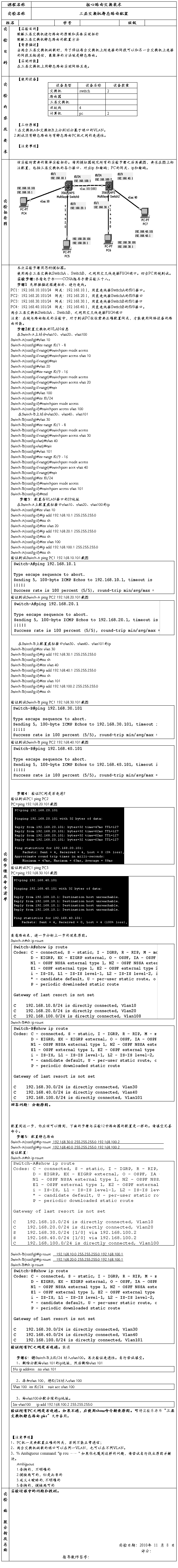
【实训拓扑】
【主要命令】
switchport mode trunk、switchport access vlan id
【实训步骤】
1、在交换机( S2126A) SwitchA 上创建 Vlan 10,并将 0/1 端口划分到 Vlan 10 中。
Switch#
Switch#configure terminal !进入全局配置模式。
Switch(config)#hostname SwitchA
SwitchA(config)# vlan 10 !创建 Vlan 10。
SwitchA(config-vlan)#exit
SwitchA(config)#interface fastethernet 0/1 !进入接口配置模式。
SwitchA(config-if)#switchport access vlan 10 !将 0/1 端口划分到 Vlan 10。
SwitchA(config-if)#end
验证测试:验证已创建了 Vlan 10,并将 0/1 端口已划分到 Vlan 10 中。
SwitchA#show vlan id 10
VLAN Name Status Ports
---- -------------------------------- --------- -------------------------------
10 VLAN0010 active Fa0/1
2、在交换机( S2126B) SwitchB上创建 Vlan 20,并将 0/1 端口划分到 Vlan 20 中。
Switch#
Switch#configure terminal !进入全局配置模式。
Switch(config)#hostname SwitchB
SwitchB(config)# vlan 20 !创建 Vlan 20。
SwitchB(config-vlan)#exit
SwitchB(config)#interface fastethernet 0/1 !进入接口配置模式。
SwitchB(config-if)#switchport access vlan 20 !将 0/1 端口划分到 Vlan 20。
SwitchB(config-if)#end
验证测试:验证已创建了 Vlan 20,并将 0/2 端口已划分到 Vlan 20 中。
SwitchB#show vlan id 20
VLAN Name Status Ports
---- -------------------------------- --------- -------------------------------
20 VLAN0020 active Fa0/1
3、在交换机 SwitchA 、 SwitchB 与交换机3760( SwitchC)相连的端口(0/23、 0/24端口)定义为 tag vlan 模式。
SwitchA#
SwitchA#conf t
SwitchA(config)#interface fastethernet 0/24 !进入接口配置模式。
SwitchA(config-if)#switchport mode trunk !将 fastethernet 0/24 端口设为 tag vlan 模式。
验证测试:验证fastethernet 0/24 端口已被设置为tag vlan模式。
SwitchA#show interfaces fastEthernet 0/24 switchport
Interface Switchport Mode Access Native Protected VLAN lists
---------- ---------- --------- ------- -------- --------- --------------------
Fa0/24 Enabled Trunk 1 1 Disabled All
SwitchB#
SwitchB#conf t
SwitchB(config)#interface fastethernet 0/23 !进入接口配置模式。
SwitchB(config-if)#switchport mode trunk !将 fastethernet 0/23 端口设为 tag vlan 模式。
验证测试:验证fastethernet 0/23 端口已被设置为tag vlan模式。
SwitchB#show interfaces fastEthernet 0/23 switchport
Interface Switchport Mode Access Native Protected VLAN lists
---------- ---------- --------- ------- -------- --------- --------------------
Fa0/23 Enabled Trunk 1 1 Disabled All
4、在交换机 SwitchC 上将与 SwitchA、 SwitchB相连的端口(0/23、 0/24 端口)定义为 tag vlan 模式。
Switch#
Switch#conf
Switch (config)#host SwitchC
SwitchC(config)#interface fastethernet 0/23 !进入接口配置模式。
SwitchC(config-if)#switchport mode trunk !将fastethernet 0/23端口设为tag vlan 模式。
SwitchC(config)#interface fastethernet 0/24 !进入接口配置模式。
SwitchC(config-if)#switchport mode trunk !将fastethernet 0/24端口设为tag vlan 模式。
SwitchC(config-if)#end
验证测试:
验证 fastethernet 0/23 端口已被设置为tag vlan模式。
Switchc#show interfaces fastEthernet 0/23 switchport
Interface Switchport Mode Access Native Protected VLAN lists
---------- ---------- --------- -------- --------- --------------------
Fa0/23 Enabled Trunk 1 1 Disabled All
验证 fastethernet 0/24 端口已被设置为tag vlan模式。
Switchc#show interfaces fastEthernet 0/24 switchport
Interface Switchport Mode Access Native Protected VLAN lists
---------- ---------- --------- -------- --------- --------------------
Fa0/24 Enabled Trunk 1 1 Disabled All
5、验证 PC1 与 PC2不能互相通信。
C:\>ping 192.168.10.10 !从 PC2 ping PC1
Pinging 192.168.10.10 with 32 bytes of data:
Request timed out.
Request timed out.
Request timed out.
Request timed out.
Ping statistics for 192.168.10.10:
Packets: Sent = 4, Received = 0, Lost = 4 (100% loss),
6、设置三层交换机 VLAN 间通讯。
在交换机 SwitchC 上创建Vlan 10、 Vlan 20 并配置IP地址
SwitchC#configure terminal !进入全局配置模式。
SwitchC(config)# vlan 10 !创建 Vlan 10。
SwitchC(config-vlan)#exit
SwitchC # configure terminal !进入全局配置模式。
SwitchC(config)# vlan 20 !创建 Vlan 20。
SwitchC(config-vlan)#exit
SwitchC(config)#int vlan 10
Switchc(config-if)#ip add 192.168.10.1 255.255.255.0
Switchc(config-if)#no sh
Switchc(config-if)#exit
SwitchC(config)#int vlan 20
SwitchC(config-if)#ip add 192.168.20.1 255.255.255.0
SwitchC(config-if)#no sh
SwitchC(config-if)#exit
SwitchC(config)#
7、将 PC1 和 PC2 的默认网关设置为 192.168.10.1,将 PC2 的默认网关设置为:192.168.20.1。
8、测试结果。不同 VLAN 内的主机可以互相PING通。
C:\>ping 192.168.10.10
Pinging 192.168.10.10 with 32 bytes of data:
Reply from 192.168.10.10: bytes=32 time=19ms TTL=126
Reply from 192.168.10.10: bytes=32 time=20ms TTL=126
Reply from 192.168.10.10: bytes=32 time=21ms TTL=126
Reply from 192.168.10.10: bytes=32 time=20ms TTL=126
Ping statistics for 192.168.10.10:
Packets: Sent = 4, Received = 4, Lost = 0 (0% loss),
Approximate round trip times in milli-seconds:
Minimum = 19ms, Maximum = 21ms, Average = 20ms
路由器静态路由配置
【实训背景】
学校有新旧两个校区,每个校区是一个独立的局域网,为了使新旧校区能够正常相互通讯,共享资源。每个校区出口利用一台路由器进行连接,两台路由器间学校申请了一条2M的DDN专线进行相连,要求你做适当配置实现两个校区间的正常相互访问。
【实训目的】
掌握静态路由的配置方法和技巧,熟悉广域网线缆的连接方式。
【技术原理】
路由器属于网络层设备,能够根据IP包头的信息,选择一条最佳路径,将数据包转发出去。实现不同网段的主机之间的互相访问。
路由器是根据路由表进行选路和转发的。而路由表里就是由一条条的路由信息组成。 路由表的产生方式一般有3种:
直连路由给路由器接口配置一个IP地址,路由器自动产生本接口IP所在网段的路由信息。
静态路由在拓扑结构简单的网络中,网管员通过手工的方式配置本路由器未知网段的路由信息,从而实现不同网段之间的连接。
动态路由协议学习产生的路由在大规模的网络中,或网络拓扑相对复杂的情况下,通过在路由器上运行动态路由协议,路由器之间互相自动学习产生路由信息。
【实训内容】
1、按照拓扑进行网络连接
2、配置路由器的接口地址参数
3、配置静态路由
4、测试
【实现功能】
实现网络的互连互通,从而实现信息的共享和传递。
【实训设备】
R1762(2台),PC(2台)、直连线(2条)、V.35线缆(1对)
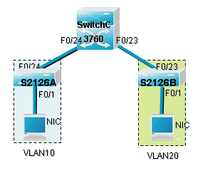
【实训拓扑】
【主要命令】
Ip route ,clock rate , no shutdown, ip address
【实训步骤】
1、在路由器 Router1 上配置接口的 IP 地址和串口上的时钟频率。
router#conf
router#host Router1
Router1(config)# interface fastethernet 1/0 !进入接口fastethernet 1/0的配置模式
Router1(config-if)# ip address 192.168.1.1 255.255.255.0 !配置路由器接口fastethernet 1/0的 IP 地址
Router1(config)# no shutdown !开启路由器 fastethernet0 接口
Router1(config)# interface serial 1/2 !进入接口 S1/2 配置模式
Router1(config-if)# ip address 192.168.2.1 255.255.255.0 !配置路由器接口 S1/2 的 IP 地址
Router1(config-if)#clock rate 64000 !配置 Router1 的时钟频率(DCE)
Router1(config)# no shutdown !开启路由器serial 1/2接口
Router1(config)#end
验证测试:验证路由器接口的配置
Router1#show ip interface brief
Interface IP-Address(Pri) OK? Status
serial 1/2 192.168.2.1/24 YES UP
serial 1/3 no address YES DOWN
FastEthernet 1/0 192.168.1.1/24 YES UP
FastEthernet 1/1 no address YES DOWN
Null 0 no address YES UP
Router1#show interface serial 1/2
serial 1/2 is UP , line protocol is UP
Hardware is PQ2 SCC HDLC CONTROLLER serial
Interface address is: 192.168.2.1/24
MTU 1500 bytes, BW 20## Kbit
Encapsulation protocol is HDLC, loopback not set
Keepalive interval is 10 sec , set
Carrier delay is 2 sec
RXload is 1 ,Txload is 1
Queueing strategy: WFQ
5 minutes input rate 15 bits/sec, 0 packets/sec
5 minutes output rate 17 bits/sec, 0 packets/sec
1030 packets input, 22660 bytes, 0 no buffer
Received 1030 broadcasts, 0 runts, 0 giants
14 input errors, 1 CRC, 12 frame, 0 overrun, 1 abort
1031 packets output, 22682 bytes, 0 underruns
0 output errors, 0 collisions, 3 interface resets
1 carrier transitions
V35 DCE cable
DCD=up DSR=up DTR=up RTS=up CTS=up
2、在路由器 Router1 上配置静态路由。
Router1#conf
Router1(config)#ip route 192.168.3.0 255.255.255.0 192.168.2.2
或:
Router1(config)#ip route 192.168.3.0 255.255.255.0 serial 1/2
验证测试:验证 Router1 上的静态路由配置
Router1#show ip route
Codes: C - connected, S - static, R - RIP
O - OSPF, IA - OSPF inter area
N1 - OSPF NSSA external type 1, N2 - OSPF NSSA external type 2
E1 - OSPF external type 1, E2 - OSPF external type 2
* - candidate default
Gateway of last resort is no set
C 172.16.1.0/24 is directly connected, FastEthernet 1/0
C 172.16.1.1/32 is local host.
C 172.16.2.0/24 is directly connected, serial 1/2
C 172.16.2.1/32 is local host.
S 172.16.3.0/24 [1/0] via 172.16.2.2
3、 在路由器 Router2 上配置接口的 IP 地址和串口上的IP 地址。
router# conf
router# hostname Router2
Router2(config)#
Router2(config)# interface fastethernet 1/0!进入接口fastethernet 1/0 的配置模式
Router2(config-if)# ip address 192.168.3.1 255.255.255.0 !配置路由器接口fastethernet 1/0的 IP 地址
Router2(config)# no shutdown !开启路由器 fastethernet0 接口
Router2(config)# interface serial 1/2 !进入接口 S1/2 配置模式
Router2(config-if)# ip address 192.168.2.2 255.255.255.0 !配置路由器接口 S1/2 的 IP 地址
Router2(config)# no shutdown !开启路由器serial 1/2 接口
Router2(config)#end
验证测试:验证路由器接口的配置
Router2#show ip interface brief
Interface IP-Address(Pri) OK? Status
serial 1/2 192.168.2.2/24 YES UP
serial 1/3 no address YES DOWN
FastEthernet 1/0 192.168.3.1/24 YES UP
FastEthernet 1/1 no address YES DOWN
Null 0 no address YES UP
Router2#show interface serial 1/2
serial 1/2 is UP , line protocol is UP
Hardware is PQ2 SCC HDLC CONTROLLER serial
Interface address is: 192.168.2.2/24
MTU 1500 bytes, BW 20## Kbit
Encapsulation protocol is HDLC, loopback not set
Keepalive interval is 10 sec , set
Carrier delay is 2 sec
RXload is 1 ,Txload is 1
Queueing strategy: WFQ
5 minutes input rate 17 bits/sec, 0 packets/sec
5 minutes output rate 17 bits/sec, 0 packets/sec
1082 packets input, 23804 bytes, 0 res lack, 0 no buffer,0 dropped
Received 1082 broadcasts, 0 runts, 0 giants
1 input errors, 0 CRC, 1 frame, 0 overrun, 0 abort
1082 packets output, 23804 bytes, 0 underruns,0 dropped
0 output errors, 0 collisions, 3 interface resets
1 carrier transitions
V35 DTE cable
DCD=up DSR=up DTR=up RTS=up CTS=up
4、 在路由器 Router2 上配置静态路由。
Router2#conf
Router2(config)#ip route 192.168.1.0 255.255.255.0 192.168.2.1
或:
Router2(config)#ip route 192.168.1.0 255.255.255.0 serial 1/2
验证测试:验证 Router2 上的静态路由配置
Router2#show ip route
Codes: C - connected, S - static, R - RIP
O - OSPF, IA - OSPF inter area
N1 - OSPF NSSA external type 1, N2 - OSPF NSSA external type 2
E1 - OSPF external type 1, E2 - OSPF external type 2
* - candidate default
Gateway of last resort is no set
S 192.168.1.0/24 [1/0] via 192.168.2.1
C 192.168.2.0/24 is directly connected, serial 1/2
C 192.168.2.2/32 is local host.
C 192.168.3.0/24 is directly connected, FastEthernet 1/0
C 192.168.3.1/32 is local host.
5、 测试网络的互连互通性。
C:\>ping 192.168.3.20 !从 PC1 ping PC2
C:\>ping 192.168.3.20
Pinging 192.168.3.20 with 32 bytes of data:
Reply from 192.168.3.20: bytes=32 time=19ms TTL=126
Reply from 192.168.3.20: bytes=32 time=20ms TTL=126
Reply from 192.168.3.20: bytes=32 time=21ms TTL=126
Reply from 192.168.3.20: bytes=32 time=20ms TTL=126
Ping statistics for 192.168.3.20:
Packets: Sent = 4, Received = 4, Lost = 0 (0% loss),
Approximate round trip times in milli-seconds:
Minimum = 19ms, Maximum = 21ms, Average = 20ms
C:\>ping 192.168.1.10 !从 PC2 ping PC1
Pinging 192.168.1.10 with 32 bytes of data:
Reply from 192.168.1.10: bytes=32 time=19ms TTL=126
Reply from 192.168.1.10: bytes=32 time=20ms TTL=126
Reply from 192.168.1.10: bytes=32 time=21ms TTL=126
Reply from 192.168.1.10: bytes=32 time=20ms TTL=126
Ping statistics for 192.168.1.10:
Packets: Sent = 4, Received = 4, Lost = 0 (0% loss),
Approximate round trip times in milli-seconds:
Minimum = 19ms, Maximum = 21ms, Average = 20ms
背景介绍:
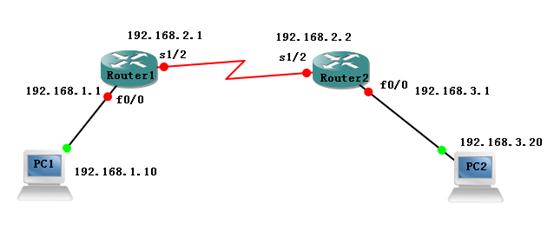
下图为某学校网络拓扑模拟图,接入层设备采用S2126G交换机,在接入交换机上划分了办公网VLAN20和学生网VLAN30。为了保证网络的稳定性,接入层和汇聚层通过两条链路相连,汇聚层交换机采用S3550,汇聚层交换机通过VLAN1中的接口F0/10与RA相连,RA通过广域网口和RB相连。RB以太网口连接一台FTP服务器。通过路由协议,实现全网的互通。
说明
上图中实验设备端口均为假设路由器为R1762,在部分实验环境中,如果路由器为R2620系列,上图中F1/0端口对应为R2620的F0,S1/2端口对应为R2620的S0端口。
实验要求
1、 在S3550与S2126两台设备创建相应的VLAN。(15分)
a) S2126的VLAN20包含F0/1-5端口;
b) S2126的VLAN30包含F0/6-10端口;
c) 在S3550上创建VLAN80;
d) 将F0/18-20 ,F0/22加入到VLAN80。
2、 S3550与S2126两台设备利用F0/23与F0/24建立TRUNK链路(10分)
a) S2126的F0/23和S3550的F0/23建立TRUNK链路;
b) S2126的F0/24和S3550的F0/24建立TRUNK链路。
3、 S3550与S2126两台设备之间提供冗余链路(10分)
a) 配置快速生成树协议实现冗余链路;
b) 将S3550设置为根交换机。
4、 在RA和RB上配置接口IP地址(10分)
a) 根据拓扑要求为每个接口配置IP地址
b) 保证所有配置的接口状态为UP
5、 配置三层交换机的路由功能(12分)
a) 配置S3550实现VLAN20、VLAN30、VLAN80之间的互通;(7分)
b) S3550通过VLAN1中的F0/10接口和RA相连,在S3550上ping路由器A的F1/0地址,ping通得(5分)。
6、 运用RIPV2路由协议配置全网路由(18分)
a) 在S3550、路由器A、路由器B上,能够学习到网络中所有网段信息。
注意事项
本考试以结果为导向,配置过程和网络运行结果在分数中的均占一定比重,为避免没有show出结果导致失分,请务必运行以下show命令。
在S2126上运行show spanning-tree show running-config
在3550上运行 show running-config show spanning-tree
show ip route ping 10.1.1.1
在RA和RB上运行show running-conifg show ip interface brief
show ip route
题号: 1 本题分数:7.69 分
请输入S2126交换机 show spanning-tree 的结果
题号: 2 本题分数:7.69 分
请输入S2126交换机 show running-config 的结果
题号: 3 本题分数:7.69 分
请输入3550交换机 show running-config的结果
题号: 4 本题分数:7.69 分
请输入S3550交换机 show spanning-tree的结果
题号: 5 本题分数:7.69 分
请输入S3550交换机 show ip route 的结果
题号: 6 本题分数:7.69 分
请输入S3550交换机 ping 10.1.1.1的结果
题号: 7 本题分数:7.69 分
请输入RA路由器 show running-conifg 的结果
题号: 8 本题分数:7.69 分
请输入RB路由器 show running-conifg 的结果
题号: 9 本题分数:7.69 分
请输入RA路由器 show ip interface brief的结果
题号: 10 本题分数:7.69 分
请输入RB交换机 show ip interface brief的结果
题号: 11 本题分数:7.69 分
请输入RA路由器 show ip route 的结果
题号: 12 本题分数:7.69 分
请输入RB路由器 show ip route 的结果
题号: 13 本题分数:7.69 分
实验配置参考:
1、 在S3550与S2126两台设备创建相应的VLAN。(15分)
S2126配置参考:
switch(config)#vlan 20
switch(config-vlan)#exit
switch(config)#vlan 30
switch(config-vlan)#exit
switch(config)#interface range fastEthernet 0/1-5
switch(config-if-range)#switchport access vlan 20
switch(config-if-range)#exit
switch(config)#interface range fastEthernet 0/6-10
switch(config-if-range)#switchport access vlan 30
switch(config-if-range)#exit
switch(config)#hostname S2126
S2126(config)#
S3550配置参考:
switch(config)#vlan 80
switch(config-vlan)#exit
switch(config)#interface range fastEthernet 0/18-20,0/22
switch(config-if-range)#switchport access vlan 80
switch(config-if-range)#exit
switch(config)#hostname S3550
S3550(config)#
2、 S3550与S2126两台设备利用F0/23与F0/24建立TRUNK链路
S2126配置参考:
S2126(config)# interface range fastEthernet 0/23-24
S2126(config-if-range)#switchport mode trunk
S2126(config-if-range)#exit
S2126(config)#
S3550配置参考:
S3550(config)# interface range fastEthernet 0/23-24
S3550(config-if-range)#switchport mode trunk
S3550(config-if-range)#exit
S3550(config)#
3、 S3550与S2126两台设备之间提供冗余链路(10分)
S2126配置参考:
S2126(config)#spanning-tree
S2126(config)#spanning-tree mode rstp
S3550配置参考:
S3550(config)#spanning-tree
S3550(config)#spanning-tree mode rstp
S3550(config)#spanning-tree priority 0
4、 在RA和RB上配置接口IP地址(10分)
RA配置参考:
router(config)#hostname RA
RA(config)#interface fastEthernet 1/0
RA(config-if)#ip address 10.1.1.1 255.255.255.0
RA(config-if)#no shutdown
RA(config-if)#exit
RA(config)#interface serial 1/2
RA(config-if)#ip address 192.168.1.1 255.255.255.252
RA(config-if)#no shutdown
RA(config-if)#exit
RA(config)#
RB配置参考:
router(config)#hostname RB
RB(config)#interface fastEthernet 1/0
RB(config-if)#ip address 1.1.1.1 255.255.255.0
RB(config-if)#no shutdown
RB(config-if)#exit
RB(config)#interface serial 1/2
RB(config-if)#ip address 192.168.1.2 255.255.255.252
RB(config-if)#no shutdown
RB(config-if)#exit
RB(config)#
5、 配置三层交换机的路由功能(12分)
S3550配置参考:
switch(config)#hostname S3550
S3550(config)#vlan 20
S3550(config-vlan)#exit
S3550(config)#vlan 30
S3550(config-vlan)#exit
S3550(config)#interface vlan 1
S3550(config-if)#ip address 10.1.1.2 255.255.255.0
S3550(config-if)#no shutdown
S3550(config-if)#exit
S3550(config)#interface vlan 20
S3550(config-if)#ip address 192.168.20.1 255.255.255.0
S3550(config-if)#no shutdown
S3550(config-if)#exit
S3550(config)#interface vlan 30
S3550(config-if)#ip address 192.168.30.1 255.255.255.0
S3550(config-if)#no shutdown
S3550(config-if)#exit
S3550(config)#interface vlan 80
S3550(config-if)#ip address 192.168.80.1 255.255.255.0
S3550(config-if)#no shutdown
S3550(config-if)#end
S3550#ping 10.1.1.1
6、 运用RIPV2路由协议配置全网路由(18分)
S3550配置参考:
S3550(config)#router rip
S3550(config-router)#network 192.168.20.0
S3550(config-router)#network 192.168.30.0
S3550(config-router)#network 192.168.80.0
S3550(config-router)#network 10.0.0.0
S3550(config-router)#version 2
S3550(config-router)#exit
S3550(config)#
RA配置参考:
RA(config)#router rip
RA(config-router)#network 10.0.0.0
RA(config-router)#network 192.168.1.0
RA(config-router)#version 2
RA(config-router)#exit
RA(config)#
RB配置参考:
RB(config)#router rip
RB(config-router)#network 1.0.0.0
RB(config-router)#network 192.168.1.0
RB(config-router)#version 2
RB(config-router)#exit
RB(config)#