美国农业部信息采集和发布制度简介
美国已经建立了完善的农业统计体系,形成了以美国农业部(USDA)及其所属的国家农业统计局(NASS)、经济研究局(ERS)、海外农业局(FAS)、农业市场服务局(AMS)、世界农业展望委员会(WAOB)、农场服务局(FSA)、首席信息办公室等机构为主体的信息收集、分析、发布工作体系。美国农业部与全国44个州的农业部门合作,设立了100多个信息收集办事处并配备专职的市场报告员,负责收集、审核和发布全国农产品信息。其提供的市场信息涉及120多个国家、60多个品种,涵盖主要农产品的全球产量、国内产量、供求情况、价格变化等情况,并在法定的日子里公布,农民可以通过网络、电话和邮寄等方式,得到完整的市场信息。
一、农业信息收集机制
(一)立法实现信息共享。美国从信息资源采集到发布均实行立法管理,并不断完善这种体系。19xx年美国农业市场法案授权规定,凡享受政府补贴的农民和农业生产者,都有义务向政府提供农产品产销信息。
(二)统一的调查方案。美国实行联邦和州两级立法与议会、政府和联邦行政机关多层次立法的体制,保证全国农业统计在调查方法、调查项目、调查时间、调查口径等方面的一致性、可比性、唯一性、权威性。 (三)规范化的调查程序。美国农业调查的基本程序是:调查人员培训→实地调查→基层调查及编辑→上报州统计办公室→州统计办公室编辑(通常采用电脑软件自动检验审核与统计师总结审核相结合,有问题立即返工或调查)→预计→报告农业部统计局→统计局审核→编辑统计资料→分析评估→发布共享。
(四)全面、翔实的信息调查内容。信息调查内容涵盖:农牧产品价格、支出、劳动力及其工资情况,农业生产与效率、收入、成本与开支、消费与利用情况,土地价值与土地使用情况,种植业与畜牧业生产测算,农场合作组织情况,市场新闻,国外农业情况,农业资金平衡情况等。
二、农业信息分析机制
(一)定性与定量相结合的预报分析。美国农业部建立了农产品供需平衡表制度,这一制度结合了定量化的商品模型预测、定性的专家判断以及分析人员的深层次研究。模型选取的背景变量涵盖本行业和相关行业的最新市场信息和经济指标,以及反映本国重大的政治、经济政策变化与全球政策变化交互作用的综合指标。
(二)规范的信息处理。美国农业部信息的第一手资料大多依靠其有关业务局的抽样调查得出,对抽样数据按照一定比重推算得出全国的数据,然后参照普查数据进行验算校正。
(三)封闭的预报分析。美国农业部采取封闭研讨方式预报分析市场敏感的主要农产品品种。商品评估综合协调委员会(ICEC)每月召开一次“过夜的封闭会议”,估计分析汇总结果,形成平衡预测报告。
另外,美国农业部统计局作物生产报告和世界农业供需评估报告也是全封闭起草,并在每个月指定时间发布。依照美国法律规定,在信息公布之前,任何人不得泄漏报告的内容,违反者要受到经济和刑事处罚。
三、农业信息发布机制
(一)严格的信息发布制度。美国政府对农业信息发布的时间、程序等都有着严格的制度和规定。美国国会要求,美国农业部每个月都要对世界农产品的供求形势进行一次预测。在每个月的第2个星期,来自农业部各部门的专家,必须在特定的时间内进入一个全封闭的会议室里,先将国内各州送来的生产调查资料开封,再配合全球市场产销态势,审定各产品的预测数字,最后达成代表农业部的官方预测,以报告方式对外公告。
(二)信息发布的权威性。美国农业部及其所属相关机构承担信息发布职能,其发布的国家一级数据必须与国家农业统计局和世界展望委员会发布的数据一致,并在发布前得到机构间的批准,确保发布信息的权威性。各州统计办公室只能发布由国家农业统计局认可的统计资料,而无权发布其他任何资料。由于所有调查资料汇总由下而上,数据发布由上而下,从而避免了数据冲突。
(三)信息发布快速且途径多样。在NASS和WAOB信息发布的第一时间里,通讯社记者在封闭区内就会把有关作物生产和预测报告用电子化方式发布出去;同时,NASS和WAOB也会在信息发布之后快速将报告放入互联网。报告还以传真、电子邮件和书面形式提供。此外,每个机构都建立了一个查询服务站,来确保公众或用户能够现场咨询并得到快速答复。
(四)重视预报后偏差的评估与用户反馈。WAOB定期对预报进行深入分析与评估,以计算预报偏差。美国农业部每年召开一次例会介绍公众关心的问题,并征求意见,同时接受电话或书信提问。
四、利益分配机制 (一)公众无偿提供信息,保密使用。所有被调查者均有义务按要求无偿提供有关信息。如果企业或个人提供的数据失真,将会影响到他们的诚信度甚至是享受的有关政府补贴。统计部门对于调查者提供的数据承担相应的法律保密责任,所有农业统计调查的个体数字是不对外提供的,有些个体数字甚至在汇总上报后消除。 (二)信息使用兼顾公益性和市场化。官方的信息服务由财政支持,通常是免费的,如农业部及其所属相关机构向社会发布的政策法规、统计数据、市场动态等方面的信息是免费的。其他非政府公共服务职能信息绝大多数都是有偿的,信息的价值大小取决于信息的有用性和指导性。因此,在美国存在许多农业信息和咨询公司。
五、对我国农业统计的启示
一是制定法律,完善信息获取渠道。美国获取农业信息的渠道比较通畅,能够掌握各种翔实的信息,从而为其分析预测提供了较为准确的信息,如美国农业部在全国拥有200多万个农场主的基本数据资料库。
对我国来说,应强化农业信息共享的法律和法规建设,保证一些基础性的信息能够及时、准确地收集上来;开辟多种信息获取渠道,为政府部门、涉农企业、科研人员、市场分析人员、投资分析人员等提供决策服务。 二是成立部门间信息管理与协调小组,保证信息的权威性和一致性。美国农业部成立了商品评估综合协调委员会(ICEC),负责国家农业统计局、农业市场局、海外农业局、农业经济研究局、世界农业展望委员会、农场服务局等机构的农业信息管理与协调工作。通过制定规定保证他们所做的工作不受其他任何部门指使或管理。当前我国采集发布农业信息的部门有多个,数据信息一致性有待提高,信息的权威性有待加强。
三是加大农业信息体系建设投资,强化农业信息公共服务。美国的农业部及其所属机构的工作人员都属于公务员编制,他们的工作经费都有财政支持。我国应明确农业信息统计、发布等工作的公共服务定位,进一步加大农业信息的资金扶持力度,发挥好农业统计在指导生产和促进流通中的作用
第二篇:外文翻译---数据采集:简介
附录A 英文文献原文
Data Acquisition: An Introduction
Bruxton Corporation
This is an informal introduction digital data acquisition hardware. It is primarily directed towards assisting in the selection of appropriate hardware for recording with the Acquire program. Overview
In principle, data acquisition hardware is quite simple. An A/D converter delivers a sequence of values representing an analog signal to an acquisition program. In practice, selecting and properly using data acquisition hardware is more complex. This document provides an informal introduction to the topic.
Contents
Background 1
From Sensors to Signals 2
From Signals to Samples 2
From Samples to Computer 4.Measurement Accuracy 5
Many of the examples are taken from patch-clamp recording. This technique requires
accurate acquisition of low-level signals (picoamperes) with bandwidth in the audio range (up to 10kHz).
Background
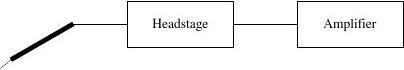
A data acquisition system converts a AmplifierDigitizersignal derived from a sensor into a sequence sensor
+3.250of digital values. The sensor is connected to +3.100an amplifier, which converts the signal into a +2.500
+1.745potential. The amplifier is in turn connected +0.985to a digitizer, which contains an A/D
converter. The digitizer produces a sequence of values representing the signal.
Signal Source
The source of most signals to be digitized is a sensor, connected to an amplifier with appropriate signal conditioning. The amplifier delivers an electrical signal. This signal is then digitized using an A/D converter.
For patch-clamp recording, the sensors are solution filled pipettes. The pipette is connected to a patch-clamp amplifier that converts the voltage at the pipette or the current through the pipette to a high-level signal. By convention, the full-scale output range of a patch-clamp amplifier is ±10V, matching the range of common instrumentation quality digitizers.
Digitizer
A digitizer converts one or more channels of analog signal to a sequence of corresponding digital values. The heart of a digitizer is an A/D converter, a device that samples an analog signal and converts the sample to a digital value.
For example, for recording from a single ion channel, the digitizer might determine the output of the patch clamp amplifier once every 50ms and provide the resulting value to the computer.
Sampling Theorem
The purpose of data
acquisition is to analyze an analog
signal in digital form. For this to
be possible, the sequence of
values produced by a digitizer
must represent the original analog
signal.
The sampling theorem states that this is the case. The sampling theorem states that an analog signal can be reconstructed from a sequence of samples taken at a uniform interval, as long as the sampling frequency is no less than double the signal bandwidth. For example, assume a signal contains frequencies from DC (0Hz) to 10kHz. This signal must be sampled at a rate of at least 20kHz to be reconstructed properly.
As a practical matter, the sampling rate should be several times the minimum sampling rate for the highest frequency of interest. For example, to resolve a 10kHz signal, a minimum sampling rate of 20kHz is required, but a sampling rate of 50kHz or more should be used in practice. Control
Most of this discussion is about digitizing analog signals for a computer. In many cases, a computer also produces analog control signals. For example, in patch-clamp experiments involving voltage-gated ion channels, the computer is frequently used to produce an electrical stimulus to activate the channels. These control signals are produced using a D/A (digital to analog) converter.
From Sensors to Signals
Many signal sources consist of a sensor and an amplifier. The amplifier converts the output of the sensor into the signal to be digitized.
Preamplifier
Many instrumentation systems
are built with a preamplifier located as close to the sensor as possible. A
separate amplifier converts the
Microelectrodepreamplifier output to a high-level
signal. Placing the preamplifier close to the sensor reduces noise, by allowing the signal to be amplified before being sent over a cable. Since physical space near the sensor is limited, the preamplifier is as small as possible, with the bulk of the electronics being located in the amplifier.
For example, in a patch clamp setup, the sensor is a solution-filled pipette, the preamplifier is the head stage, and the amplifier is the patch-clamp amplifier itself.
Signal Conditioning
Many sensors deliver signals that must be transformed before they can be digitized. For example, a microelectrode pipette may be used to measure current, while the digitizer measures potential (voltage). The patch clamp amplifier provides a current-to-voltage amplification, usually

measured in mV of output per pA of input. This transformation of the sensor signal is called signal
conditioning.
Signal conditioning may be more complex. An input signal from a non-linear sensor may be converted to a voltage that is linear in the quantity being measured, compensation may be made for second-order effects such as temperature, or an indirect effect such as a frequency shift may be converted to a voltage.
Integrated Digitizer
As the cost of A/D converters declines, the digitizing function can be moved into the amplifier. For example, the HEKA elektronik EPC-9 patch-clamp amplifier contains a built in digitizing unit (an Instrutech ITC-16).
Integrating a digitizer into an amplifier can substantially reduce total noise in the digitized signal, since the analog signal is not carried over a cable from the amplifier to an external digitizer. Be careful of instrument specifications when comparing an analog amplifier to one with a built-in digitizer. Including the digital electronics in the amplifier housing may increase noise, and the digitizer itself may add noise to the signal. However, the total noise in the digitized signal may be much less than if an external digitizer is used. Compare an amplifier with an integrated digitizer to the combination of an analog amplifier and an external digitizer.
A major advantage of integrating a digitizer into an amplifier is that the amplifier designer can easily include features for computer control. A data acquisition program connected to such an amplifier can then offer an integrated user interface, simplifying operation. In addition, the acquisition program can record all amplifier settings, simplifying data analysis.
From Signals to Samples
A digitizer consists of an A/D (analog to digital) converter that samples an analog input signal and converts it to a sequence of digital values.
Aliasing
The sampling theorem states that, in order to be able to reconstruct a signal, the sampling rate must be at least twice the signal bandwidth. What happens if a signal contains components at a frequency higher than half the sampling frequency? The frequency components above half the sampling rate appear at a lower frequency in the sampled data.
The apparent frequency of a sampled signal is the actual frequency modulo half of the sampling rate. For example, if a 26kHz signal is sampled at 50kHz, it appears to be a 1kHz signal in the sampled data. This effect is called aliasing.
Anti-Aliasing Filter
If a signal to be digitized has components at frequencies greater than the half the sampling frequency, an anti aliasing filter is required to reduce the signal band width. The anti-aliasing filter must cut off signal components above one half the sampling rate.
Most signal sources are inherently band-limited, so in practice, anti-aliasing filters are often not required. However, some signal sources produce broadband noise that must be removed by an anti-aliasing filter.
For example, patch-clamp amplifiers have built-in anti aliasing filters. The pipette used for patch-clamp recording inherently filters signals above a low frequency in the range of 1kHz. The good high frequency response of a patch clamp amplifier is achieved only by boosting the high frequency component of the signal to compensate for the frequency response of the pipette. This can produce significant high-frequency noise. A patch-clamp amplifier provides a filter to eliminate this noise.
Integrating Converters
The discussion of aliasing assumes instantaneous sampling. The output value produced by the A/D is represents the instantaneous analog signal amplitude. Such sampling A/D converters are the most common for use in instrumentation.
Some A/D converters employ an integrating conversion technique. The output value produced by such a digitizer represents the integral of the analog signal amplitude over the sampling interval. Such converters eliminate aliasing. They can be viewed as containing a built-in anti-aliasing filter.
Integrating converters are rarely used in high-speed control applications. The most common techniques for implementing high-speed integrating converters result in a delay of many sample intervals between an analog sample and the corresponding digitizer output value. This delay can introduce considerable phase shift at high frequencies in closed-loop response if the digitizer is used in a control system.
Resolution
Typically a digitizer provides the computer with fixed length binary numbers. For example, the Axon Instruments Digidata 1200A produces 12-bit numbers, while the Instrutech Corporation ITC-16 produces 16-bit numbers. The length of each value is called the resolution of the device, measured in bits.
The resolution can be translated to an absolute input level. Most digitizers measure swings of up to approximately 10V from zero, for a total range of 20V. A 12-bit value has a resolution of 1 part in 4096, so the resolution of a 12-bit digitizer is 20V divided by 4096, or approximately 5mV. This is expressed by saying that a change of one count (or one least significant bit, or LSB) represents 5mV.
Digitizer Resolution(+10V Range)
Resolution
8 bits
10 bits
12 bits
14 bits
16 bits18 bitsDistinct Values2561024409616384655362621441 LSB(approximate)80mV20mV5mV1.25mV300μV75μV
Since analog instruments rarely have an accuracy significantly exceeding 0.1%, it might seem that 10 or 11 bit resolution would be sufficient in a digitizer. However, additional bits of resolution are needed because the input signal frequently does not use the entire input range. For example, even if the instrumentation amplifier gain has been adjusted to yield an input signal with a 20V range, small components of the signal with a 2V range might also be of interest.0.1% resolution of a 2V signal within a 20V range requires at least 13 bits of resolution.
Accuracy
Several specifications are used to express the accuracy of a digitizer.
The absolute accuracy expresses how precisely the digital values produced represent the analog inputs. For example, a digitizer might have an absolute accuracy of 1 part in 4096. This can also be expressed by saying that the digitizer has 12 bit absolute accuracy.
The relative accuracy expresses how precisely the digitizer measures the difference between two analog input values. This is frequently of greater interest than the absolute accuracy.
The noise specification expresses how much the digitizer output will vary with no change in the analog input. This is frequently expressed as a number of bits. For example, a 16-bit digitizer with two bits of noise will produce effectively the same results as a 14-bit digitizer.
The accuracy of a digitizer varies strongly with its maximum sampling rate. The more accurate the digitizer, the slower it is.
Be careful when reading digitizer specifications. In some cases, manufacturers publish specifications of the A/D converter used in a digitizer as the specifications for the entire digitizer. However, the accuracy of the digitizer may be significantly less. The digitizer may include necessary components such as amplifiers and voltage references that degrade the accuracy. In addition, the A/D specifications apply only under specific conditions described in the converter datasheet. In the digitizer, those conditions may not apply.
From Samples to Computer
Once data has been digitized, it must be transferred to a computer. Usually a digitizer is built as a computer plug in board, so transfers take place over the computer bus.
Digitizers used for high-speed measurement can feed data to the computer at a high and constant rate. For example, a digitizer running on one channel at 100k samples/second will typically produce 200k bytes/second of data continuously. This is a large stream of data.
The continuous nature of much data acquisition requires some kind of buffering. For example, if the computer stops for 30ms to write data to disk or to update a display, 6000 bytes of data will accumulate. The data must be stored somewhere, or it will be lost.
Data Transfer: DMA
The Axon Instruments Digidata 1200 uses DMA (direct memory access) to transfer data to the memory of the host computer. DMA transfers proceed regardless of the activity in the host.
DMA transfers encounter problems on during 4K Pagecontinuous acquisition. The problem is that the DMA
4K Pagecontroller used on PC motherboards is only capable of
transferring data to a contiguous block of memory. However,
Microsoft Windows 95 and Windows NT use allocate Digitizermemory in 4K byte pages. A data acquisition program might
have a large buffer, but the buffer will be scattered 4K byte 4K Pagepages in physical memory. The DMA controller can transfer
to only one page at a time. When done with a page, it
interrupts the host computer. The device driver for the
4K Pagedigitizer must then reload the DMA controller for the next
page. Computer Memory
Normally these periodic interrupts are not a problem.
For example, even at the full 330kHz rate of the Digidata 1200, a 4K page is filled only every 6ms. The interrupt handling in the driver might take 50us on a fast processor. Less than 1% of the time of the processor is taken servicing interrupts.
However, a problem occurs under multitasking operating systems such as Microsoft Windows NT, because many other activities can take place simultaneously. If another device driver is performing processing and has locked out interrupts temporarily, the digitizer device driver may have to wait to service the DMA controller.
To deal with this problem, Axon Instruments has increased the buffer memory in the
Digidata from 2K samples in the Digidata 1200 to 8K samples in the 1200A and 1200B. This increase allows the unit to buffer data for up to 24ms even at 330kHz, avoiding problems. Data Transfer: Buffers
The Instrutech Corporation ITC-16 and ITC-18 do not use DMA. Instead, they use a large buffer to hold data until it can be processed by the host computer. The data is then transferred to the host computer by programmed I/O. That is, the device driver performs the transfer. On current computers, programmed I/O is about as efficient as DMA. These computers are generally limited in performance by the memory system. Therefore, even through a DMA transfer occurs without the intervention of the host computer, the transfer ties up the memory, which effectively stalls the processor. The Instrutech digitizers do not provide interrupts to the host computer. Instead, host computer periodically polls the device to obtain data. This polling is performed periodically by the application program (i.e. HEKA Pulse or Bruxton Corporation Acquire. Since the polling may be infrequent, the digitizer needs a large buffer. For example ,if a program can poll the digitizer only once every 100ms,the digitizer must have a 20000 sample memory to operate at 200kHz.The Instrutech ITC-16 has a 16k sample FIFO. The Instrutech ITC-18 is available with either a 256k sample FIFO or a 1M sample FIFO.
Data Transfer: PCI Bus Mastering
Some PCI bus data acquisition boards can write data directly into the memory of the host computer using bus mastering. Bus master data transfers do not use the motherboard DMA controller, and therefore can potentially support writing directly to a buffer composed of discontiguous 4K pages. In the future, bus master designs are likely to become popular. Those familiar with computer system design will notice that the PCI bus master transfers are in fact direct memory access (DMA) transfers. On PC systems, for historical reasons, the term DMA refers to the use of the DMA controller built in to the motherboard.
Data Transfer: Output
The discussion so far has concentrated on data transfer for acquired data. If the digitizer is used for synchronous stimulation or control, the same data transfer problem occurs as for acquiring data. In fact, the total data rate doubles. Consider, for example, a stimulus/response measurement on one channel with a 100kHz sampling rate. Acquired data is received by the computer at 100kHz. Simultaneously, the stimulus waveform must be delivered by the computer to the digitizer at 100kHz. The full data rate 200kHz.The Axon Instruments and Instrutech digitizers have symmetric handling of inputs and outputs. The output buffers are the same size as the input buffers, and the same data transfer technique is used.
Measurement Accuracy
The following sections discuss the issues that influence the accuracy of dynamic measurements.
Crosstalk
Most digitizers record from multiple analog input channels, with 8 or 16 input channels being commonly supported. An important specification is the crosstalk between input channels, that is, the amount of input signal from one channel that appears on another channel.
Crosstalk is a problem because many Multiplexer
Channel Adigitizers use a single analog to digital
Channel Bconverter, and a switch called a
A/Dmultiplexer to select between input Channel C
Channel Dconverter
channels.
The multiplexer itself is a source of crosstalk. Even when a switch is open, capacitive coupling between the input of the switch and the output of the multiplexer produces a frequency-dependent crosstalk. High-frequency input signals are coupled to the multiplexer output even when they are not selected.
To measure such crosstalk, ground an analog input and sample from it. Meanwhile, connect a high-frequency signal to other input channels. Notice the amplitude of the high-frequency signal that appears on the grounded input. This is the crosstalk. Vary the input frequency and notice the change in the amount of crosstalk.
Crosstalk may not be significant when a digitizer is used for patch-clamp data acquisition. Typically one analog input is used for the ion channel signal, while other analog inputs are used to measure very low-frequency signals. The low-frequency signals do not couple significantly to the ion channel signal. The ion channel signal does couple into the low-frequency channels, but this can generally be eliminated by averaging many input samples on those channels.
If you measure on several channels containing high frequency data, characterize the crosstalk of your data acquisition system before you do so. Otherwise you may find yourself measuring correlations in input data due to your digitizer instead of the system being measured.
This problem will become less significant with time, as the cost of A/D converters drops. Digitizer manufacturers can afford to place one A/D converter for each input channel, avoiding the use of a multiplexer.
Settling Time
The settling time of the A/D converter input may limit the rate of multi-channel sampling. The input amplifiers on many A/D Multiplexerconverters cannot follow very high Afrequency input signals. When the Bmultiplexer switches channels, this appears C
as a sudden jump in signal level to the input D
of the A/D converter. At low sampling rates,
the A/D input will have considerable time to settle before converting the next sample. At high sampling rates, the input may not have time to settle, and the input signal on one channel affects the value measured on the next.
To see this effect, ground all inputs of a digitizer except one. Connect this input to a variable DC level. Sample at a high rate on multiple channels. Notice if changing the input level on one channel causes the value measured on one of the grounded channels to change.
Frequently, digitizers achieve full bandwidth only when the multiplexer is not being used, and the digitizer is sampling from only a single input channel.
The Axon Instruments Digidata 1200A/B and the Instrutech Corporation ITC-16 both use a single A/D converter and a multiplexer. The Instrutech Corporation ITC-18 uses a separate A/D converter per input channel. While this raises the cost of the device, it essentially eliminates crosstalk.
Grounding
The digitizer is electrically part of your instrumentation system. This can cause problems if you do not consider the digitizer when planning the grounding of your instrumentation.
If your digitizer is used only for acquisition, you can take advantage of differential analog

inputs to avoid connecting your digitizer directly to your measurement ground through signal cables. However, if you use the analog outputs of your digitizer this may not be possible, since analog outputs are rarely differential.
Analog outputs are particularly a problem if the digitizer ground is the same as the computer ground. Computer ground lines usually transmit high-frequency switching noise. The noise can be coupled through the common ground into your measurement system. This is a common failing of low-cost digitizer boards.
The Instrutech ITC-16 and ITC-18 use optical isolation in the digital control path of the digitizer. This completely isolates the measurement system from the computer ground. Input Impedance
The FET-based input amplifiers used in modern digitizers have a very high input impedance. If inputs are left unconnected, they can pick up unwanted signals and couple them into the digitizer.
The Axon Instruments Digidata 1200A/B and the Instrutech ITC-16 have very high impedance analog inputs. For best results, unused inputs on these devices should be grounded.
The Instrutech ITC-18 has bleed resistors connected internally between the analog inputs and ground to reduce pickup of stray signals. Grounding of unused analog inputs is less critical with this device.
Phase
If you are sampling from multiple input channels, you may be interested in the phase relationship between the inputs.
Digitizers that use a single multiplexed A/D converter inherently have a delay between measurements on different input channels. For example, if two channels are being sampled, each at interval T, most multiplexer-based digitizers will sample successive channels at interval T/2. Sample number N on channel A and sample number N on channel B will be separated in time by T/2.
For most applications, this delay is not of concern. However, in some cases the phase relationship between signals is of interest.
To limit the phase shift between channels, you can ample at a very high rate. If you can sample quickly enough, you can minimize the delay between samples.
An alternative solution is to sample from successive channels at high speed in a burst. Some digitizers provide sophisticated internal timers that allow you to sample a group of channels quickly, then delay for the next sample. For example, suppose your sampling rate is 1kHz on four channels. With most digitizers, you would sample at an interval of 250ms. However, if your digitizer has the capability, you could sample the four channels at an interval of only 10ms, then wait until a full 1000ms interval has elapsed before the next sample.
You can also correct for the error in software. You maybe able to adjust your calculations for the delay. For example, the HEKA Pulse program is aware of some of the delays in the Instrutech ITC-16, and adjusts for them.
The best solution is to use a digitizer without a multiplexer. Some digitizers, such as the Instrutech ITC-18 and the Markenrich CL522, provide an A/D converter for each input channel. This allows all channels to be sampled simultaneously, with no delay. Using multiple A/D converters is by far the best solution, but it is also the most expensive.
Synchronization
Digitizers may provide analog outputs used for stimulation and control. The analog outputs are updated at the same rate the analog inputs are sampled, and have sufficient buffering to allow continuous stimulation while recording.
When using a digitizer to measure the response of a system to a stimulus, be aware of the time relationship between stimulation and sampling. Two effects must be considered: the pipeline and the device timing.
Digitizers generally have pipelines of input and output samples. For example, the A/D converter usually delivers a digitized data value while it converts the next value. Data values may be temporarily buffered in internal registers while being transferred. This usually leads to a delay of three to five samples in a pipeline.
To see the effect of this pipeline, suppose that at a stimulus value appears on one of the digitizer outputs. Simultaneously an analog input is sampled. Even if the system being measured has no delay, several sample times will pass before the analog input value resulting from the stimulus passes through the pipeline. When measuring the response of a system to a stimulus, this delay must be taken into account. Depending on the digitizer design, this delay may be a function of the number of channels being sampled or stimulated.
Analog input sampling and analog output update may not be simultaneous. The designer of a digitizer usually tries to minimize analog input measurement noise. When analog outputs are updated, the transition may cause electrical disturbances that appear as noise on the analog inputs. Capacitive coupling from the outputs to the input can appear as noise on the inputs. Noise can also be a result of coupling through the power supply or ground.
A simple technique to minimize this noise is to choose the phase relationship of sampling and update to allow as much time to pass following an update before the next sample. For example, if the sampling interval is T, the analog inputs might be sampled at time 0 and the analog outputs might be updated at time T/2.
If you are interested in measuring the response of a system to a stimulus precisely, you will have to obtain information from the vendor regarding the synchronization of stimulation and response.
附录B 英文文献译文
数据采集:简介
Bruxton公司
这是一个非正式引入数字数据采集硬件。它主要是针对用于记录与收购计划协助在选择适当的硬件。
概观
原则上,数据采集硬件是相当简单的.一个的A / D转换器提供了一个序列值代表一个模拟信号的取样。在实践中,选择和正确使用数据采集硬件更为复杂。本文提供了一个非正式的介绍。
内容
背 景 1 前级扩大机 2从信号到采样 2从采样到传输到电脑 4
许多例子都取自膜片钳记录。这种技术需要准确地采集低电平信号(皮安),音频范围内的带宽(高达10kHz)。 背景
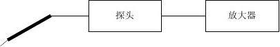
一种数据采集系统中的信号转换成一个数字值序列来自从传感器的。该传感器连接到一个放大器,该放大器的信号转换成一个潜在的。该放大器是依次连接到数字转换器,其中包含一个A / D转换器使用数字转换器产生的序列的值,表示信号。
测量精度 5
器
放大器
数字转换
器+3.250+3.100+2.500+1.745+0.985
信号源
大多数被数字化的信号源传感器,都被连接到一个放大器调节.放大器提供一个电信号。然后,这个信号用一个A / D转换器数字化。
对于膜片钳记录中,传感器解决方案充满移液器。吸移管被连接到上面的移液管或高电平信号通过移液管的电流电压转换的一个膜片钳放大器。按照惯例,一个膜片钳放大器的满量程输出范围为±10V,相匹配的一系列常见的仪表质量数字化仪。
数字转换器
甲数字转换器转换成一个或多个通道的模拟信号相应的数字值序列。数字化仪的心脏是一个A / D转换器,一个装置的模拟信号进行采样,并将其转换为数字值的样本
例如,数字化仪,用于记录从一个单一的离子通道,可能确定每50ms一次的膜片钳放大器的输出,并提供所得到的值的计算机。
采样定理
数据采集的目的是分析以数字形式的模拟信号。这是可能的,数字转换器产生的序列的值必须代表原来的模拟信号。
采样定理指出,这是一个模拟信号的情形。采样定理指出,从一个序列的样本以均匀的
时间间隔,只要采样频率可重构是不小于两倍的信号带宽。例如,假设一个信号包含的频率从直流(0Hz的)到10kHz。这个信号必须被采样的速率至少为20kHz的正确重建。
作为一个实际问题,采
样率应该是几次感兴趣的最
高频率的最小采样速率。例
如,要解决一个10kHz的信
号,需要的最小采样速率为
20kHz,但在实践中,应使用
的采样速率为50kHz或更。
控制
在此讨论中的是模拟信号数字化的计算机。在许多情况下,计算机也可以产生模拟控制信号。例如,在膜片钳实验中电压门控离子通道,计算机被频繁地使用,以产生电刺激激活的通道。这些控制信号都采用一个D / A(数字到模拟)转换器。
从传感器到信号
许多信号源包括一个感应器和一个放大器。该放大器的输出转换到的信号进行数字化的传感器。
前置放大器
位于尽可能接近传感器前置
放大器都建有许多仪器仪表系统。
一个单独的放大器,前置放大器转
换输出到一个高层次的信号。名次微电极接近传感器前置放大器,降低了噪
音,通过允许要被放大的信号通过电缆之前被发送。由于在传感器附近的物理空间是有限的,在前置放大器是尽可能的小,与散装位于在放大器的电子设备。
例如,在膜片钳设置,传感器是一个充满溶液的吸液管,前置放大器是头阶段,且放大器膜片钳放大器本身。
信号调节
许多传感器提供的信号才可以被数字化,必须转变。例如,一个微电极移液管可用于测量电流,而数字化仪测量电位(电压)。膜片钳放大器提供了电流 - 电压放大,通常以每PA的输入输出mV的。这种变换的传感器信号被称为信号调理。
信号调理可能会更复杂。一个非线性传感器的输入信号可被转换成的电压是线性的被测量的量,补偿可以由二阶影响,如温度,或间接的影响,如频移可被转换成的电压。 集成的数字化仪
作为A / D转换下降的成本,数字化功能可以被移动到放大器。例如,HEKA电子的EPC-9膜片钳放大器包含一个内置的数字化设备(InstruTech产品ITC-16)。
数字转换器集成到一个放大器可以大幅降低总噪声的数字化信号中,由于模拟信号通过电缆不进行从放大器到一个外部数字转换器。小心仪器规格比较时,一个内置的数字化模拟放大器。包括数字化电子放大器外壳可能会增加噪声和数字转换器本身可能会增加噪音的信号。然而,在数字化的信号的总噪声可能会远小于,如果一个外部数字转换器的使用。在一个放大器的一个集成的数字转换器的组合的模拟放大器和一个外部的数字化仪进行比较。
数字化仪集成到一个放大器的一个主要优点是,放大器设计师可以很容易地包括电脑控制的功能。此类放大器连接到一个数据采集程序,可以再提供一个集成的用户界面,简化了操作。此外,收购程序,可以记录所有的放大器的设置,简化了数据分析。

从信号到采样
甲数字转换器包括一个A / D(模拟到数字)转换器进行采样的模拟输入信号,将其转换为一个数字值序列。
混叠
采样定理的状态,以便能够重构信号,采样速率必须是至少两倍于信号带宽。如果一个信号包含的频率高于采样频率的一半分量,会发生什么事?采样率的一半以上的频率分量出现在较低的频率采样数据。
的表观频率的采样信号的实际频率的模数采样率的一半。例如,如果一个26kHz的信号进行采样,在50kHz,它似乎是1kHz的信号的采样数据的。这种效应被称为混叠。 抗混叠滤波器
如果以进行数字化的信号成分在频率大于半采样频率,抗混叠滤波器是必需的,以减少信号带宽。抗混叠滤波器,必须切断上述信号分量的采样率的一半。
大多数信号源固有的频带受限的,所以在实践中,抗混叠滤波器也常常不是必需的。然而,一些信号源产生宽带噪声,必须除去一个抗混叠滤波器。
例如,膜片钳放大器内置抗混叠滤波器。膜片钳记录用于吸移管固有的过滤上述取值范围为1kHz的低频信号。膜片钳放大器的良好的高频响应来实现仅由升压的高频分量的信号,以补偿的移液管的频率响应。这可能会产生明显的高频噪声。一个补丁钳放大器提供了一个过滤器来消除这种噪声。
集成转换器
讨论混叠时假定瞬时采样。产生的输出值,由A / D转换是指瞬时模拟信号幅度。这种采样的A / D转换器是最常见的用于仪器仪表。
有些A / D转换器采用积分转换技术。这样的数字转换器所产生的输出值表示在采样间隔的模拟信号幅度的积分。这种转换器消除锯齿。它们可以被看作是包含一个内置的抗混叠滤波器的。
很少用于高速控制的应用集成转换器。最常用的技术用于实现高速积分转换结果之间的模拟采样和相应的数字转换器的输出值的采样间隔的延迟。这种延迟可以推出,如果数字转换器的控制系统中使用的闭环响应在高频率中的相当大的相移。
分辨率
通常,数字化仪提供的计算机,固定长度的二进制数。例如,Axon的仪器Digidata 1200A产生12位的数字,而InstruTech产品公司ITC-16产生16位的数字。每个值的长度被称为的移动设备,以位为单位的分辨率。
分辨率可以翻译成一个绝对的输入电平。大多数数字化仪测量摆幅高达从零到约10V,20V的总范围。一个12位的值,分辨率为4096分之1,所以一个12位数字化仪的分辨率20V除以4096,或大约为5mV。这表示说,一项改变(或至少显着位,或LSB)表示为5mV。
数字转换器分辨率(+10 V范围)
分辨率
8 bits
10 bits
12 bits
14 bits
16 bits18 bits区分值2561024409616384655362621441 LSB(近似值)80mV20mV5mV1.25mV300μV75μV
由于很少有模拟仪器的精度显着超过0.1%,它似乎是数字化在一个10位或11位分辨
率范围内就足够了。然而,更精确的分辨率是必要的,因为输入信号经常不在整个输入范围。例如,即使仪表放大器的增益已被调整,以产生与一个20V的范围内的输入信号,用2V范围内的小元件发出的也可能是一个分辨率为0.1%的范围在2V到 20V内的信号,而其至少需要有13位的分辨率。
准确性
几种规格被用于表达特定的数字化仪的精度。
如何精确的数字值代表模拟输入的绝对精度表示。例如,可能具有数字化转换器4096的1份,其绝对精度。这也可以说,数字化仪有12位绝对精度表示。
相对精度表示,如何精确的数字化测量两个模拟输入值之间的差异。这通常是比绝对精度更大的兴趣。
噪声规范表示数字转换器的输出会随模拟输入没有变化多少。这是经常表示为比特数。例如,一个16位的数字转换器与两位噪声将有效地产生一个14位数字化仪相同的结果。
数字化仪的准确度,变化很大,它的最大采样速率。更精确的数字化,慢。
阅读数字化仪规格时一定要小心。在某些情况下,制造商发布了A / D转换器中使用数字化仪作为整个数字化仪规格的标准。然而,数字化仪的准确度可能会显着地减少。数字化仪可以包括必要的元件,如放大器和基准电压源,降低的准确性。此外,A/ D规格仅适用于特定的条件下转换器数据手册中的描述。在数字化,这些条件可能不适用。
从采样到传输到电脑
一旦数据被数字化,必须将其传送到计算机上。数字化仪通常内置的电脑插件板,所以转让发生在计算机总线。
用于测量高速数字化仪可以养活高和恒定速率的数据传输到计算机。例如,数字化仪上运行的一个信道在100k的样本/秒的通常会连续产生200k的字节/秒的数据。这是一个大的数据流。
连续性质多的数据采集需要某种缓冲。例如,如果计算机停止30ms的数据写入到磁盘或更新显示,6000字节的数据就会聚积起来。数据必须存储在某个地方,或将丢失。 数据传输:DMA
Axon的仪器Digidata1200使用DMA(直接存储4K 页
器访问)将数据传输到电脑主机的记忆。的DMA传输4K 页着手无论几近主机。
DMA传输上遇到的问题,在连续收购。的问题是,数字转换使用PC主板上的DMA控制器只能够将数据传送到一器
个连续的内存块。然而,微软的Windows95和Windows 4K 页NT使用4K字节页分配内存。数据采集程序可能有一
个大的缓冲区,但缓冲区将分散在物理内存中的4K
字节页。 DMA控制器可以转移到只有一个页面的时间。
当完成一个页面时,它将中断主机。数字化的设备驱4K 页动程序,然后重新翻页DMA控制器。 计算机内存通常情况下,这些周期性的中断是不是一个问题。
例如,即使在全为330kHz的速率的Digidata1200,一个4K缓冲区加载都只需6ms。在驱动程序的中断处理快速的处理器可能需要50微秒,处理器服务中断小于1%小时。
然而,问题会在多任务操作系统,如Microsoft Windows NT,因为许多其他的活动可以同时进行。如果另一个设备驱动程序进行处理,并已锁定暂时中断,数字化设备驱动程序可能必须等待维修的DMA控制器。
为了处理这个问题,Axon仪器增加了从2K缓冲存储器Digidata的样品中至8K
Digidata1200样本中的1200A和1200B。此增加使单位来缓冲数据,即使在高达24MS为330kHz,也能够避免失真。
数据传输:缓冲器
InstruTech产品公司ITC-16和ITC-18没有使用DMA。相反,他们使用一个大的缓冲区来保存数据,直到它可以由主机处理。然后,数据传送给主计算机,由编程的I / O。即,设备驱动程序执行转移。在目前的电脑,可编程I / O效率DMA。这些计算机通常由存储系统在性能上的限制。因此,即使是通过DMA传输电脑主机的干预没有发生,转移关系的内存,从而有效地摊点处理器。InstruTech产品的数字化仪提供不中断主机。相反,电脑主机定期轮询设备获取数据。此轮询定期进行应用程序(即HEKA脉冲或Bruxton的公司收购。由于投票站可能是罕见的,数字化需要一个大的缓冲区,例如,如果一个程序可以轮询只有一次每100ms数字化,数字化仪有20000样品内存在200kHz操作。InstruTech产品ITC-16有16K采样FIFO InstruTech产品ITC-18是一个256K的采样FIFO或1M采样FIFO。 数据传输:PCI总线主控
一些PCI总线的数据采集板可以直接写入数据到上位机采用总线主控的记忆。总线主数据传输不使用主板的DMA控制器,因此有可能支持直接写入不连续4K的页面组成的缓冲区。在未来,总线主控设计有可能成为流行。那些熟悉计算机系统设计,会发现,其实直接内存访问(DMA)传输PCI总线主转移。在PC系统上,由于历史原因,长期的DMA是指使用DMA控制器内置在主板的。
数据传输:输出
到目前为止的讨论集中在数据传输采集到的数据。如果数字转换器是用于同步的刺激或控制,用于获取数据相同的数据传输发生问题。事实上,总数据速率加倍。考虑,例如,通过100kHz的采样率的一个频道上的一个激励/响应测量。接收采集的数据由计算机在100kHz。同时,激励波形必须由计算机交付到数字转换器在100kHz。全数据速率为200kHz。 Axon仪器和InstruTech产品数字化仪有对称处理输入和输出。输出缓冲器的输入缓冲器的大小相同,并使用相同的数据传输技术。
测量精度
以下各节讨论的动态测量精度的影响问题。
串扰
大多数数字化仪记录从多个模拟输入通道,8个或16个输入通道,普遍支持的。一个重要的规范是输入通道,也就是,从一个信道,出现在另一信道的输入信号的量之间的串扰。
串扰是一个问题,因为许多数字化仪使多路复用用一个单一的模拟到数字转换器,和一个开通道A
关被称为多路转换器之间进行选择输入通通道B
A/D 转换道。多路转换器本身是串扰的一个源。即使 通道C器当开关打开时,输入的开关和多路转换器的 通道D
输出之间的电容耦合产生的与频率相关的
串扰。高频输入信号被耦合到多路复用器的输出,甚至当它们没有被选中。
为了测量这种串扰,地面模拟输入和样品。同时,连接到另一输入端通道的高频信号。请注意,出现在接地的输入的高频信号的振幅。这是串扰。改变输入频率,并通知中的串扰量的变化。
串扰可能不显着的,当用于膜片钳数据采集数字化仪。通常,一个模拟输入用于离子通道信号,而其他模拟输入是用来测量非常低的低频信号。离子通道信号的低频信号没有显着
的情侣。该离子通道的信号耦合到低频率的信道,但一般都可以消除许多这些通道上的输入样本的平均。
如果测量多个通道上包含高频数据,描述数据采集系统的串扰,在你这么做之前。否则,你可能会发现自己输入数据,由于您的数字化,而不是测量系统测量的相关性。
随着时间的推移,这个问题将变得不那么重要,作为A/ D转换器的成本下降。数字化仪的制造商可以承受一个A / D转换器可用于将每个输入通道,避免了使用一个多路复用器。 建立时间
A/ D转换器输入的建立时间可能会限制多通道采样率。
许多A / D转换器的输入放大器不能多路复用按照频率非常高的输入信号。当多路转换A
器切换频道,这出现在A / D转换器的输B入端的信号电平作为一个突跳。在低采样C
率,A / D输入将有相当长的时间来解决D
之前,转换下一个样品。在高采样率,输
入可能没有时间来解决,在一个通道的输入信号的影响就下测得的值。
要看到这样的效果,所有输入接地,数字化仪,只有一个除外。连接该输入的可变DC电平。样品以很高的速率在多个渠道上。请注意,如果改变一个通道的输入电平,导致测量值改变接地通道之一。
通常情况下,数字化仪实现全带宽只有在不被使用的多路转换器,数字转换器的采样只从一个输入通道。
Axon仪器Digidata的1200A / B和InstruTech产品公司ITC-16都使用一个A / D转换器和多路复用器。公司ITC-18 InstruTech产品使用一个单独的A / D转换器,每输入通道。虽然这引起了装置的成本,它基本上消除了串扰。
接地
数字化仪电仪表系统的一部分。这可能会造成问题,如果你不考虑数字化规划时,您的仪器的接地。
如果您的数字化仪仅用于收购,你可以利用差分模拟输入,以避免直接测量地面通过信号电缆连接您的数字化。然而,如果你使用的模拟输出数字化仪这可能是可能的,因为很少差分模拟输出。
模拟输出是特别的问题,如果数字转换器的接地是相同的计算机地面。计算机接地线,通常发射高频开关噪声。噪声可以通过耦合到测量系统中的共同点。这是一个低成本数字化板的通病
InstruTech产品ITC-16和ITC-18使用的光隔离数字控制的数字化路径。这从计算机地面完全隔离了测量系统。
输入阻抗
现代数字化仪中使用的基于FET的输入放大器,具有非常高的输入阻抗。如果输入悬空,他们可以拿起不必要的信号和夫妇到数字化。
Axon仪器Digidata1200A/ B和ITC-16 InstruTech产品有非常高阻抗模拟输入。为了达到最佳效果,在这些设备上未使用的输入应接地。
InstruTech产品ITC-18泄放电阻之间的内部连接模拟输入和地面,以减少杂散信号皮卡。未使用的模拟输入接地与此设备是不太重要的。
相位
如果从多个输入通道采样之间的相位关系的输入,你可能会感兴趣。

使用单一的数字化仪,多路A/ D转换器本身有不同的输入通道之间的延时测量。例如,如果两个通道都被采样,在时间间隔T中,大多数多路转换器为基础的数字化仪,将样品在T / 2时间间隔的连续通道。样本数N通道A和通道B的采样数N将在时间上分开,由T/ 2。
对于大多数应用中,这种延迟是不关心。然而,在某些情况下,信号之间的相位关系的兴趣。
为了限制渠道之间的相移,你可以在一个非常高的速度充足。如果你可以品尝足够快的速度,你可以最大限度地减少样本之间的延迟。
一种替代的解决方案是在突发的高速连续通道采样。一些数字转换器提供先进的内部定时器,让您迅速品尝一组通道,然后延迟下一个样本。例如,假设您的采样速率为1kHz四个通道上。对于大多数数字转换器,你会品尝的时间间隔为250ms。然而,如果你的数字化仪有能力,你可以品尝到只有10毫秒的间隔四个通道,然后等待,直到一个完整的1000毫秒的时间间隔已经过去了,再下一个样品。
您也可以修正软件错误。你也许能够调整您的计算延迟。对于例如,HEKA脉冲的程序是知道的一些延误InstruTech产品ITC-16,并为他们调整。
最佳的解决方案是使用没有多路转换器的数字化仪。某些数字化仪,如InstruTech产品ITC-18和在Markenrich CL522,为每个输入通道提供一个A / D转换器。这允许所有通道同时采样,没有延迟。使用多个A/ D转换器是迄今为止最好的解决方案,但它也是最昂贵的。
同步
数字化仪可提供模拟输出,用于激励和控制。模拟输出被更新,以同样的速度的模拟输入进行采样,并有足够的缓冲,以允许同时记录连续刺激。
当使用数字化测量系统的响应刺激的激励和采样时间之间的关系,做到心中有数。必须考虑两方面的影响:管道和设备的时间。数字转换器通常具有管道的输入输出样本。例如,A/ D转换器通常提供了一个数字化的数据值,而它的下一个值转换。数据值可能会暂时缓存在内部寄存器中,而被转移。这通常会导致在管道中的延迟三至五个样品。
要看到这条管线的效果,假设在一个激励值出现在一个数字化的输出。同时模拟输入的采样。即使被测系统具有无延迟,几个采样时间将通过模拟输入值产生激励前通过通道。测量系统的响应激励时,这种延迟必须被考虑在内。根据不同的数字转换器的设计,这种延迟可能是被采样或激励的信道的数目的函数。
模拟输入采样率和模拟输出更新可能不同步。数字化仪的设计者,通常试图减少模拟量输入测量噪声。当模拟输出更新,过渡可能造成电气干扰,出现噪声对模拟输入。从输出到输入电容耦合可以显示为输入噪声。噪声可以也是通过电源或接地的耦合的结果。
一个简单的技术来减少这种噪音是选择采样和更新,让尽可能多的时间来通过下一个样品前更新后的相位关系。例如,如果采样的时间间隔为T时,模拟输入可能被采样在时间0时的模拟输出可能会更新在时间T/ 2。
如果系统对测量激励的响应有影响的话,那么必须从激励源那里去获取激励的同步信息以及响应。